Rig 101 — what’s on the bench
Each bench is a fly-on-ball LED-arena rig. A tethered fly walks on an air-supported ball at the center of a cylinder of LED panels; the panels show visual patterns, a camera watches the ball to measure how the fly walks, and an LED delivers optogenetic light. Here’s each piece.
New system, feedback welcome. These rigs are less than a month old, and much of the software running them, including Arena Studio, is only about 10 days old. Feedback about the hardware, experiments, software, or instructions will help us improve the course quickly. Please tell an instructor or open a course feedback issue.
The LED arena (the panels)
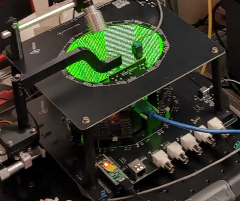
- G6 panels, arranged in 2 rows × 9 physical columns (
arena: G6_2x10). The nominal G6 model spans 10 columns, but these course rigs leave one column open directly behind the fly for the camera cable. The physical display is therefore not a full 360° ring; most arena configurations use a complete ring. - Each panel is 20 × 20 pixels. Patterns use a nominal 200-pixel azimuth coordinate system and are 40 pixels tall; one virtual column corresponds to the camera gap.
- Patterns are
.patfiles stored on the controller’s SD card. Arena Studio’s Console lists them and can play/test any one.
Course SD card: Copy the 45
.patfiles directly from the course repository’s shared pattern library to the SD-card root. Do not combine the source or separate protocol pattern folders; the shared protocol YAMLs use the library’s global IDs.
The arena controller and I/O
The controller is not a separate box. A Teensy microcontroller sits directly on the arena PCB and drives the panels, the optogenetic LED, and the digital/analog I/O. The arena is a single, self-contained experimental system: it needs only a 5 V power supply and a USB connection to the PC. Open Arena Studio in Google Chrome or Microsoft Edge, then press Connect to reach the arena.
The optogenetic LED (light stimulus)
Optostim is a low-cost, highly adjustable module built from a high-power red LED and a few simple 3D-printed parts: a mount, an adjustable slider, and a light guide. Together they provide precise positioning and full control over the direction of stimulation, so the light can be aimed reproducibly at the fly.
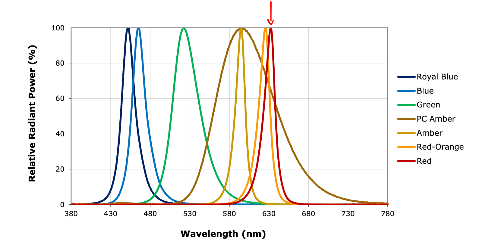
- The red arrow marks the LED used for optogenetic stimulation.
- It’s driven from the controller’s Analog Out (0–5 V) BNC through a BuckPuck/LuxDrive current driver. The driver is inverted: lower voltage = brighter.
- The rig idles the Analog Out at 5 V (LED off). Protocols set brightness as a percent (
ledDrive), which Arena Studio converts to the right voltage. - Use the LED levels specified in the assigned protocol.
The fly-on-ball tracker (FicTrac)
The fly walks on a lightweight foam ball floated on a gentle stream of air; a camera watches the ball, and FicTrac software turns its rotation into the fly’s turning, forward, and sideways motion. This is the inexpensive “spherical treadmill” from Loesche & Reiser 2021.
- Ball: a ~9 mm foam sphere (
ball_diameter_mm: 9) with a hand-marked, asymmetric pattern so FicTrac can tell every orientation apart. The diameter is what converts ball rotation into mm/s. - Air support: a 3D-printed cup/holder floats the ball. Flow is set with a regulator + a 3D-printed roller clamp. Too much flow → the ball jitters/spins wildly; too little → it sinks. Aim for a gentle, stable float.
- Camera + light: a FLIR Firefly S USB3 monochrome camera images the ball through an S-mount lens under near-infrared light — invisible to the fly, so it doesn’t pollute the visual stimulus.
- Treadmill illumination: near-infrared LEDs illuminate the ball without flicker from PWM, so the camera can track it without adding visible light to the visual stimulus.
- Bridge: a small program relays FicTrac’s motion to Arena Studio for the live oscilloscope and for closed-loop experiments (the fly steers the display). Full setup: FicTrac basics & config.
Positioning the fly
The tether clamps into an inexpensive but excellent micromanipulator above the ball. It provides fine, sub-millimeter positioning along the three translational axes, which is essential for placing a small fly carefully on the treadmill.
- Center the fly over the ball and set its height so the legs reach and grip it.
- Adjust fore-aft and left-right position so the fly is stable and comfortable.
- Align the body and gaze direction with the arena. Small errors in any axis can make the visual alignment or walking behavior harder to interpret.
Careful alignment takes practice: the fly must be positioned and oriented in several dimensions, not merely lowered onto the ball.
The tethering station
Next to the rig is the tethering station: a Peltier-cooled platform (the “sarcophagus”) under a dissecting scope, with a micromanipulator to lower the tether onto the fly. Flies are chilled on ice and glued to a pin here before going on the ball — see Tethering basics. The Fly Lab Gear tethering-station guide has the station design and component documentation.
Digital I/O BNCs
- Two “Digital IO (5V)” BNCs are integrated on the arena PCB. On course rigs, IO 1 carries a frame-scan debug pulse (handy on a scope) and IO 2 is off by default. You won’t normally touch these.
Two rig flavors
cshl_g6_2x10_ball— the fly-on-ball rig (has FicTrac). Most experiments.cshl_g6_2x10— the same arena without FicTrac (used for hardware checkout like p100).
Arena Studio uses the rig’s config to know what’s present — e.g. it only offers FicTrac closed-loop on a rig that actually has a ball tracker.
Reference
- Modular LED Display repository: https://github.com/reiserlab/Modular-LED-Display
- webDisplayTools repository: https://github.com/reiserlab/webDisplayTools
- G6 Pattern Editor: https://reiserlab.github.io/webDisplayTools/pattern_editor.html
- Loesche & Reiser (2021), An Inexpensive, High-Precision, Modular Spherical Treadmill Setup Optimized for Drosophila Experiments: doi:10.3389/fnbeh.2021.689573.
- Isaacson MD et al. (2022), A high-speed, modular display system for diverse neuroscience applications: doi:10.1101/2022.08.02.502550.
Updated 2026-07-10 02:30 ET.