Controller
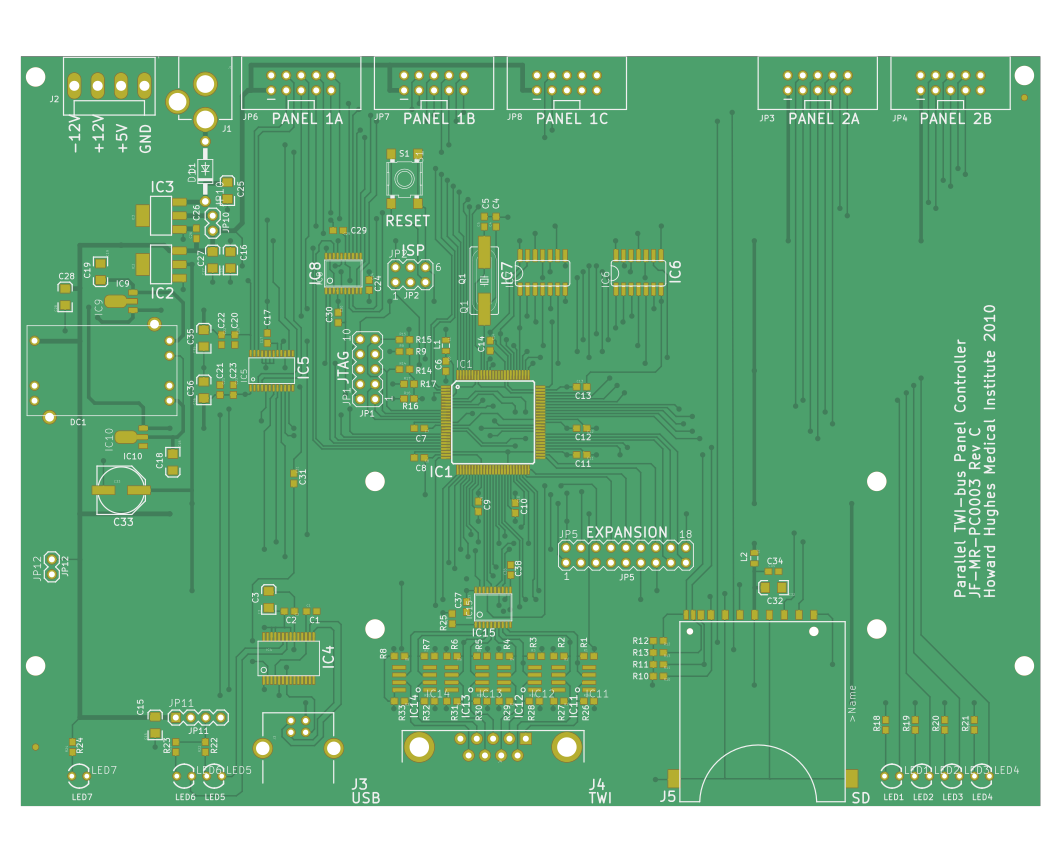
The controller receives information about the pattern that needs to be displayed from the PC via serial port and sends control messages to all connected panels.
The controller was developed under the project name JF-MR-PC0002, the most recent revision was Rev C (also see preview of the schematics). The most recent production files are archived in production_v1/JF-MR-PC0003_RevC.zip (yes, there is different number…).
- ADC0 now accepts Wing Beat Amplitude input to control X channel in modes 1 and 2. This input should be in the form of L-R. That is, with a negative gain in modes 1 and 2, a negative signal will cause a decrease in channel frame and a positive signal will cause an increase in channel frame number.
- ADC1 now accepts Wing Beat Amplitude input to control Y channel in modes 1 and 2. This will happen in the same manner as ADC0.
- ADC2 now sets the X position when the X mode is set to 3.
- ADC3 now sets the Y position when the Y mode is set to 3.
Additional functions
Two other repositories provide additional functionality for the controller: The ISP breakout board adds an interface to the controller and the possibility to directly interact with a panel board, while the BNC breakout board exposes some signals to additional BNC connectors.
Controller V 3.0 Connector functionalities list
- ADC0: analog input in mode 1 and 2 of channel x;
- ADC1: analog input in mode 1 and 2 of channel x
- ADC2: analog input in mode 1 and 2 of channel y
- ADC3: analog input in mode 1 and 2 of channel y
- ADC4: analog input in mode 3 of channel x
- ADC5: analog input in mode 3 of channel y
Note: Users can debug ADC0 to ADC5 with command Panel_com('adc_test', chan) or Panel_com('dio_test', chan)
Users can also read analog input from ADC0 to ADC3 with command Panel_com('get_adc_value', chan)
- DAC0: update current frame number (in the unit of volt) in mode 1,2,3, 4, and PC dumping mode of channel x
update analog output in mode 5 (debugging function generator) of channel x;
output triangle wave pulse to a specific ADC port with command Panel_com('adc_test', chan)
- DAC1: update current frame number (in the unit of volt) in mode 1,2,3, 4, and PC dumping mode of channel y
- update analog output in mode 5 (debugging function generator) of channel y;
- output square wave pulse to a scope with command
Panel_com('dio_test', chan) - output triangle wave pulse to a scope with command
Panel_com('adc_test', chan)
- DAC2: unused
- DAC3: unused
Note: Users can update analog output from DAC0 to DAC3 with command Panel_com('set_ao',[chan, val]);
- Int0: laser trigger;
- Int1: timing for fetching and displaying each frame when controller works in default mode and PC dumping mode
- Int2: trigger camera;
- Int3: waiting for external trigger to start pattern display
Note: Users can debug int0 to int4 with command Panel_com('dio_test', chan)
Project structure
The Eagle design files are inside the eagle folder, the production files are available in gerber.
├── eagle
└── gerber
Production
The most recent production we are aware of was ordered by the Frye lab in August 2020 at Bittele. Feel free to use the reference number Q11396B in your communication with Bittele if you want to order the exact same Controller (JF-MR-PC0003 RevC 2019_10_11) and please get in contact if you experience any problems.