Generation 3 Arena
An arena board organizes panels in a geometry and provides structural integrity to the whole setup. Different shapes of cylindrical arenas have been built. We use a naming scheme based on their number of panel columns available and the virtual ones forming a full circle. A 12-12 arena is a closed cylinder formed by 12 columns in total, a 12-20 describes an open virtual cylinder formed by 20 columns where 12 are actually available.
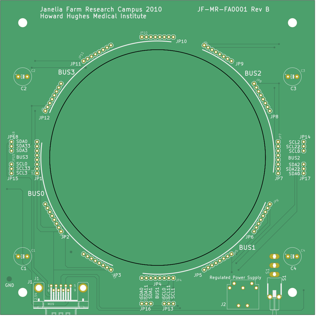
For the Generation 3, two different arenas are available: an arena 12-12 and arena 24-24. Besides the eagle project files, we provide a preview of the schematics for the arena 12-12 and the most recent production files archived in arena_12-12/production_v1/JF-MR-FA0001-RevB.zip. The same applies to the schematics of the arena 24-24 with production files archived at arena_24-24/production_v1/JF-MR-FA0002-RevA.zip.
Recommended method for assembling arenas
Assembling the LED matrix
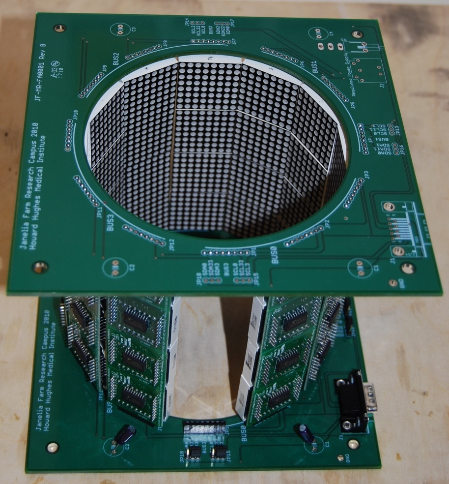
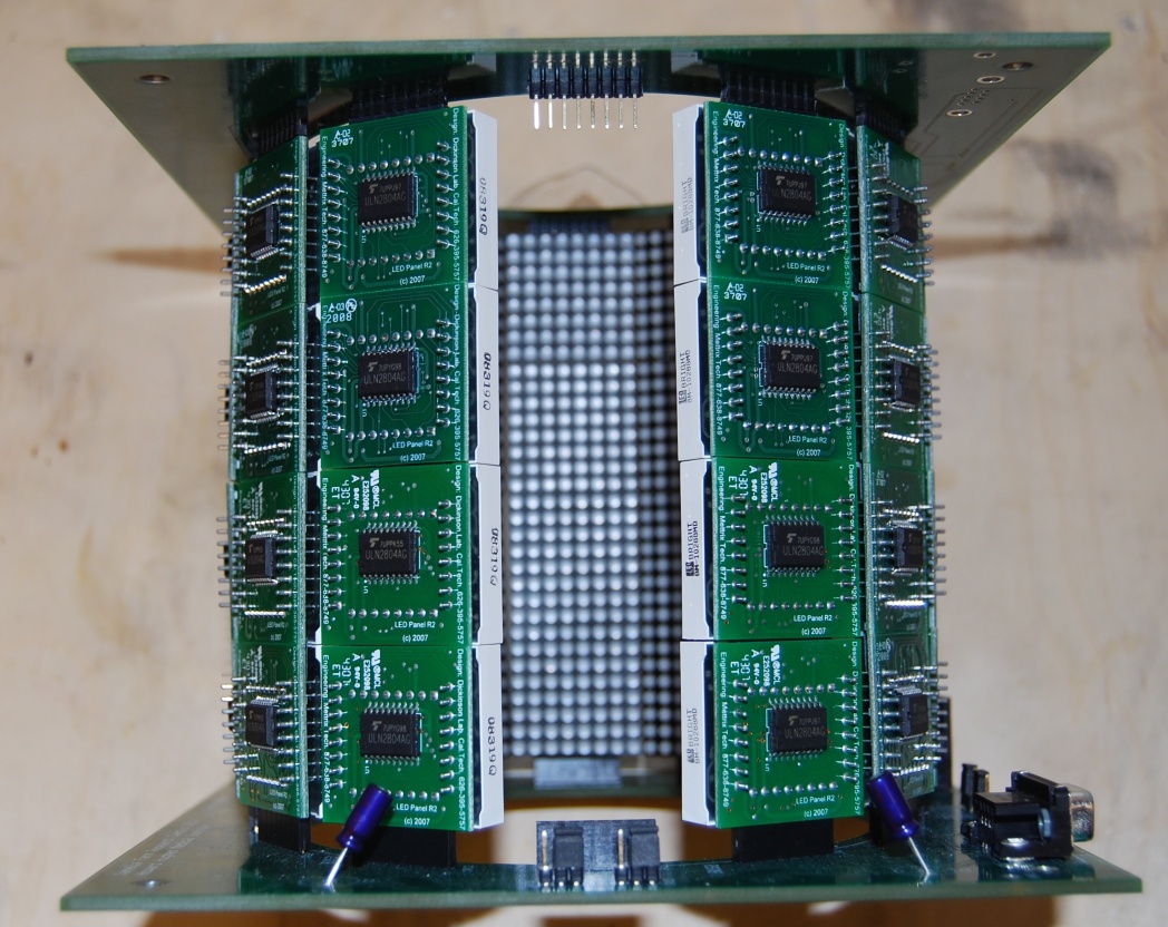
The standard arena consists of a circular array of 8×8 dot matrix displays of LEDs connected to microcontrollers in a 1:1 manner. The typical 12 panel ring arena is built from two PCB boards, and is typically 4 panels high (48 panels total). In order to later control the displays, unique addresses must be assigned to each one. These micro controllers may need to be flashed with the latest files according to the flash firmware guide before assigning addresses The following outlines the steps needed for creating a standard arena with a 4×11 array of LED displays.
- Press each LED display into the microcontroller using the correct orientation. With the male side of the controller pointing down, the ink stamp of the LED should be on the right hand side before inserting pins.
- Once 44 microcontroller/LED units have been assembled (or more, if some microcontrollers are not functioning), they must first be programmed and assigned addresses as outlined in the flash firmware guide.
- If the LED does not properly display lights, or is very dim compared to the rest, do not use it in your arena.
- Connect each column to form the 12 columns of the matrix above. This will probably require partially pulling out the LED portion of each unit, connecting the male and female ends, and then securing the LED to the microcontroller once the connection is snug. (Note this problem may make itself more apparent when viewing the assembled columns, and fixing it will ensure strong electrical connections between units).
Assembling the boards
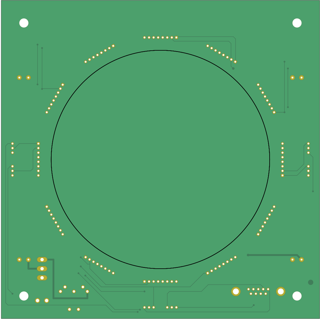
The PCB boards for each arena require some soldering. Remember both boards must be facing up in the final arena, attach components on the correct side.
- Bottom board (female end) requires 12, 8-pin stacking headers soldered around the center top (silkscreen text) circle cutout side of the board.
- Bottom board requires 4 capacitors, one in each corner of the board, with the correct polar orientation (see board, light stripe to the left).
- Bottom board also requires a power supply input, jumpering pins, a switch, serial port, and switch to be securely soldered.
- The top PCB should have male headers soldered to the bottom side (opposite the silkscreen text) that fit into the connectors of the top panels (additional components are not required on the top PCB, but capacitors are always a good idea).
- Connect the LED columns to the bottom, then top boards.
- Check that the panels turn on and are in the correct place by plugging in the 5V power supply and turning on the arena with the power switch.
- Check for gaps between LED panels which can compromise the long term stability of the arena.
Constructing the Arena Housing
Our lab uses supplies from Thorlabs to construct a holder for the arena, IR diode, IR sensor, tether post, and camera. This can be accomplished with any sturdy materials, although Thor components are recommended because of their high modularity and strength (and lab snacks). Instead of giving exact directions, some required specifications will be listed.
- The IR diode must be positioned pointing directly down on the center of the arena.
- The IR sensor must be positioned directly under the center of the arena.
- The tether post must end in the exact center of the arena with the fly between the IR diode and sensor, and at an 20-35 degree angle to the perpendicular.
- The most useful placement of a camera is level with the fly for alignment purposes.
Connecting Components
The assembled arena and remaining components must be properly connected using mainly BNC, USB and Serial Port connectors. When setting up the rest of the system, place all components in a user friendly arrangement (i.e. oscilloscope and analog camera output easily viewable). The following is a table, then diagram of connectivity. For more information on how each component works, see the Flight Simulator User Guide by Frye, Reiser, and Dickinson or read the Panels documentation page.
The following is a list of Components and connections. For example, the first line reads: the controller’s ADCO is connected to the Wing beat analyzer’s WBA input
| Component side A | Connection side A | Component side B | Connection side B |
|---|---|---|---|
| Controller | ADC0 | Wingbeat Analyzer | L |
| Controller | ADC1 | Wingbeat Analyzer | R |
| Controller | DAC0 | NI-DAQ | Input 3 |
| Controller | DAC1 | NI-DAQ | Input 4 |
| Controller | PC1 | Computer | Serial Port |
| Controller | I2C | Arena | Serial Port |
| NI-DAQ | Analog Input 0 | Wingbeat Analyzer | Amplitude L |
| NI-DAQ | Analog Input 1 | Wingbeat Analyzer | Amplitude R |
| NI-DAQ | Analog Input 2 | Wingbeat Analyzer | Frequency |
| NI-DAQ | Analog Input 3 | Controller | DAQ1 |
| NI-DAQ | Analog Input 4 | Controller | DAQ2 |
| NI-DAQ | Analog Input 5 | Wingbeat Analyzer | Amplitude L-R |
| NI-DAQ | Analog Input 6 | Analog Output 1 | |
| NI-DAQ | USB Output | Computer | USB-Port |
| NI-DAQ | Analog Output 1 | Analog Input 6 | |
| Wingbeat Analyzer | L | Controller | ADC0 |
| Wingbeat Analyzer | L | NI-DAQ | Analog Input 0 |
| Wingbeat Analyzer | R | Controller | ADC1 |
| Wingbeat Analyzer | R | NI-DAQ | Analog Input 1 |
| Wingbeat Analyzer | Signal Out L + R | Oscilloscope | Ch 1 + Ch 2 |
| Wingbeat Analyzer | Signal Out L + R | Speakers | L + R |
| Wingbeat Analyzer | L-R | Oscilloscope | Ch 3 |
| Wingbeat Analyzer | L-R | NI-DAQ | Analog Input 5 |
| Wingbeat Analyzer | SYNC (-TTL) | Oscilloscope | Ext Trig |
| Wingbeat Analyzer | LED Out | Arena | IR LED |
| Wingbeat Analyzer | Photo detector | Arena | Photo detector |
| Wingbeat Analyzer | Frequency | NI-DAQ | Analog Input 2 |
| Oscilloscope | Channel 1 | Wingbeat Analyzer | L |
| Oscilloscope | Channel 2 | Wingbeat Analyzer | R |
| Oscilloscope | Channel 3 | Wingbeat Analyzer | L-R |
| Oscilloscope | Ext Trig | Wingbeat Analyzer | SYNC (-TTL) |
| Arena | Serial Port | Controller | I2C |
| Arena | Photodetector | Wingbeat Analyzer | Photodetector |
| Arena | LED | Wingbeat Analyzer | LED Out |
| Computer | USB | NI-DAQ | |
| Computer | Serial Port | Controller | PC1 |
Power issues
(needed)