Software running on micro controller units (MCU) is considered firmware. The document guides you from obtaining the hardware to make the comm and driver panel work.
Firmware
The driver and comm board use a total of five micro controller units (MCUs). To program these five ATmega328, you will need the programmer explained in the acquisition step. This text explains, how an Arduino can be used as a “In-circuit Serial Programmer” (ISP) to flash the firmware to the driver and the comm board.
Prerequisites
You will need the following parts:
- driver board
- comm board
- Arduino
- Arduino shield
- driver board shield
- comm board shield
- (Windows) computer
Install the custom version of the Arduino IDE on your computer. This IDE has the PanelsG4 board added as a target. The Windows version of Arduino-1.6.5 is provided as an asset to “Customized Arduino IDE” release on github.
Turn Arduino into In-circuit Serial Programmer (ISP)
To flash the firmware to the panel MCUs, the Arduino will act as a programmer. For this the Arduino requires a special firmware, which is provided as “example” code. Follow these steps to turn the Arduino into an ISP.
- Connect Arduino (Make sure programmer shield is off it will prevent programming)
- Open Arduino IDE.
- Go to Tools → Board and select Arduino UNO.
- Go to Tools → Port and select correct Port
- Go to File → Examples select ArduinoISP
- Verify (check button) and Upload (right point arrow button).
These steps should be similar to what is described in an Arduino tutorial online.
Troubleshooting
There is no verbose output that helps debugging problems, but one of the three following steps solved most problems in the past:
- Make sure that the Arduino firmware has not been corrupted. Flashing the ISP firmware to the Arduino again solved many unexplained problems.
- Make sure you driver and comm boards are connected in the correct way. It’s easy to mix up polarity which, in the worst case, can corrupt a panel but is often solved by using the correct polarity.
- Makes sure only one subdevice is selected on the driver board. Multiple selections can lead to unexpected results.
Programming a comm panel
Each comm board needs to be programmed.
The following has to be done only once for all comm boards: In the the Arduino IDE and go to Tools → Board and select PanelG4. In Tools → Programmer you need to select Arduino as ISP (not ArduinoISP).
Connect comm board
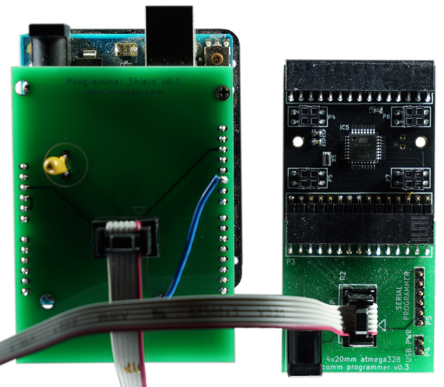
To program the ATMega328 on a comm board, connect the board to the comm shield board in a way, that you can see the components on both boards (also see image). There is no need to connect the external power supply, power is provided through the Arduino shield.
Flash comm board firmware
Once the comm board is attached to the comm shield, you can connect the comm shield to the Arduino shield with the ribbon cable. Make sure to disconnect the ribbon cable when changing the comm boards.
With the Arduino IDE open, select Tools → Burn Bootloader to write the boot loader to the comm board’s MCU. With the correct comm.ino open (the latest version is in the GitHub repository linked to this page (see link in the left bottom of the page) at hardware_v0p2/comm/), select Sketch → Upload Using Programmer. Now the comm board should be fully functional. Disconnect the ribbon cable before programming the next comm board.
Checklist for flashing comm firmware
- Connect Arduino shield to the computer1
- Open Arduino IDE
- Go to Tools → Board and select PanelG4
- Go to Tools → Programmer and select Arduino as ISP (not ArduinoISP!!!)
- Disconnect ribbon cable between comm shield board and Arduino shield
- Attach comm board to the comm shield board
- Connect the comm shield board to Arduino shield via ribbon cable2
- Go to Tools → Burn Bootloader
- Open the
comm.inosketch - Go to Sketch → Upload Using Programmer to upload sketch to comm board
- For the next comm board continue at step 5
Programming a driver panel
The following steps have to be done for each individual driver board.
The following has to be done only once for all driver boards: In the the Arduino IDE and go to Tools → Board and select PanelG4. In Tools → Programmer you need to select Arduino as ISP (not ArduinoISP).
Connect driver board

The first step is to connect the driver board to the driver board shield. The correct orientation of the driver is when the two triangles printed on the board point away from the connector (up in the picture). This will also mean, that the upper edge of the shield and the driver are well aligned and the lower edge of the driver aligns with the printed line on the shield. Make sure you double check the orientation as there is a chance of breaking the driver. There is no need to connect the external power supply, power is provided through the Arduino shield.
Flash driver board firmware

Once the driver is attached to the driver shield, you can connect the driver shield to the Arduino shield with the ribbon cable. Make sure to disconnect the ribbon cable when changing the driver board.
Select one of the four subdevices to be programmed by moving one of the dip switches away from the panel and the other three towards the panel. In the picture on the right, subdevice number 4 is selected through the dip switch on the left. Select Tools → Burn Bootloader to write the boot loader to the ATMega. With the correct driver.ino sketch opened, select Sketch → Upload Using Programmer to upload sketch to panel. Currently the latest version of the driver sketch is in the associate GitHub repository (see link in the bottom left of the page) at hardware_v0p2/driver/.
Repeat the steps for “Flash Firmware” for the other three subdevices on the same driver panel.
Checklist for flashing driver firmware
- Connect Arduino shield to the computer1
- Open Arduino IDE
- Go to Tools → Board and select PanelG4
- Go to Tools → Programmer and select Arduino as ISP (not ArduinoISP!!!)
- Connect a driver board to the driver shield board2
- Connect driver shield to the Arduino shield via ribbon cable1
- Select subdevice using dip switch. Away from the panel means “on”, only one should be up at a time3.
- Go to Tools → Burn Bootloader
- Open the
driver.inosketch - Go to Sketch → Upload Using Programmer to upload sketch to panel.
- Repeat from step a) for other subdevices
- Disconnect ribbon cable
- Repeat from step 5 for each driver board
-
Always remove ribbon cable before removing and attaching new driver subpanel as sometimes attaching a panel without doing so will corrupt the ArduinoISP program on the Arduino Uno ↩ ↩2 ↩3
-
Note, you do not need external power supply the Arduino will provide power. ↩ ↩2
-
To fully program the driver you need to program all four ATmega328’s, which means programming the bootloader and firmware for all four dip switch “on” positions, one at a time. ↩