Arena Board
The arena board organizes panels in a defined geometry and provides structural integrity to the whole setup. Different shapes of cylindrical arenas have been built. They are often described by the number of panel columns populated versus the virtual ones forming a full circle. An arena 12-12 is a closed cylinder formed by 12 columns in total. All columns can be populated in this design, but typically between 1 and 3 are left empty to access the center of the arena.
If you need a quick summary: If you want to build a G4 system, either get a 12-12 v8 (or v4) for a full cylinder, or 12-18 when you need wider field access (e.g., electrophysiology). For a G4.1 system, get the Version 10. Ignore experimental versions unless you are actively studying power or timing:
- 12-12 arenas: For most new G4 builds use Version 8. It is considered a beta version with clear advantages over existing v2 and v4 setups, and fully compatible with all Generation 4 panels (older and newer panel revisions). Version 4 is also acceptable if you want the most recent iteration of the long‑used Version 2 with added noise improvements.
- Version 10 of the 12-12 arena is a completely different system we call “G4.1”, based on an inexpensive teensy MCU instead of using a NI controller. This system is still under development.
- Stay away from other versions (1, 2C, 3, 5, 6 notch variant, 7, 9) unless you have a specific historical or research need—several were experiments and some never worked (get in contact if you want to know more).
- 12-18 arenas: Use the latest Version 1. Version 2 only changes some routing and uses hidden vias; design files are not available and fabrication is harder.
- Prototype / development arenas (6-inf, early 12-18 v0.x, voltage experiment boards): Keep these for testing or firmware bring‑up only. Do not use them for routine behavioral, imaging, or electrophysiology experiments; rely on 12-12 v8 (or v4) or 12-18 v1.1.
Below, you will find detailed historical notes starting with the 12-12 arena. The introduction here focuses only on which versions to choose today.
arena 12-12 board
A 12-12 Arena places twelve columns of panels in a regular dodecagon, forming an approximate cylindrical display with 170mm diameter. These arenas are useful for behavioral experiments.
Legacy deployments mostly use Version 2 (often updated with v2.4 production files) and the notched mechanical variant Version 6. Version 4 adds noise reduction and is a practical variation of Version 2. Versions 7 and 9 were power experiments. Version 8 is the first stable KiCad redesign compatible with older panels and is the recommended choice for new builds. Version 10 is an inexpensive and much slower system still in development; treat it as experimental and do not use it yet for routine work.
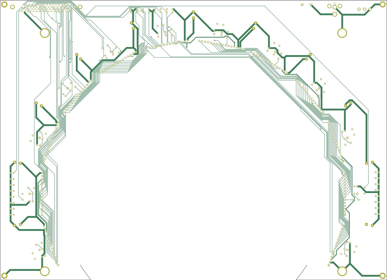
Arena 12-12 Version 1 (G4 Release Candidate)
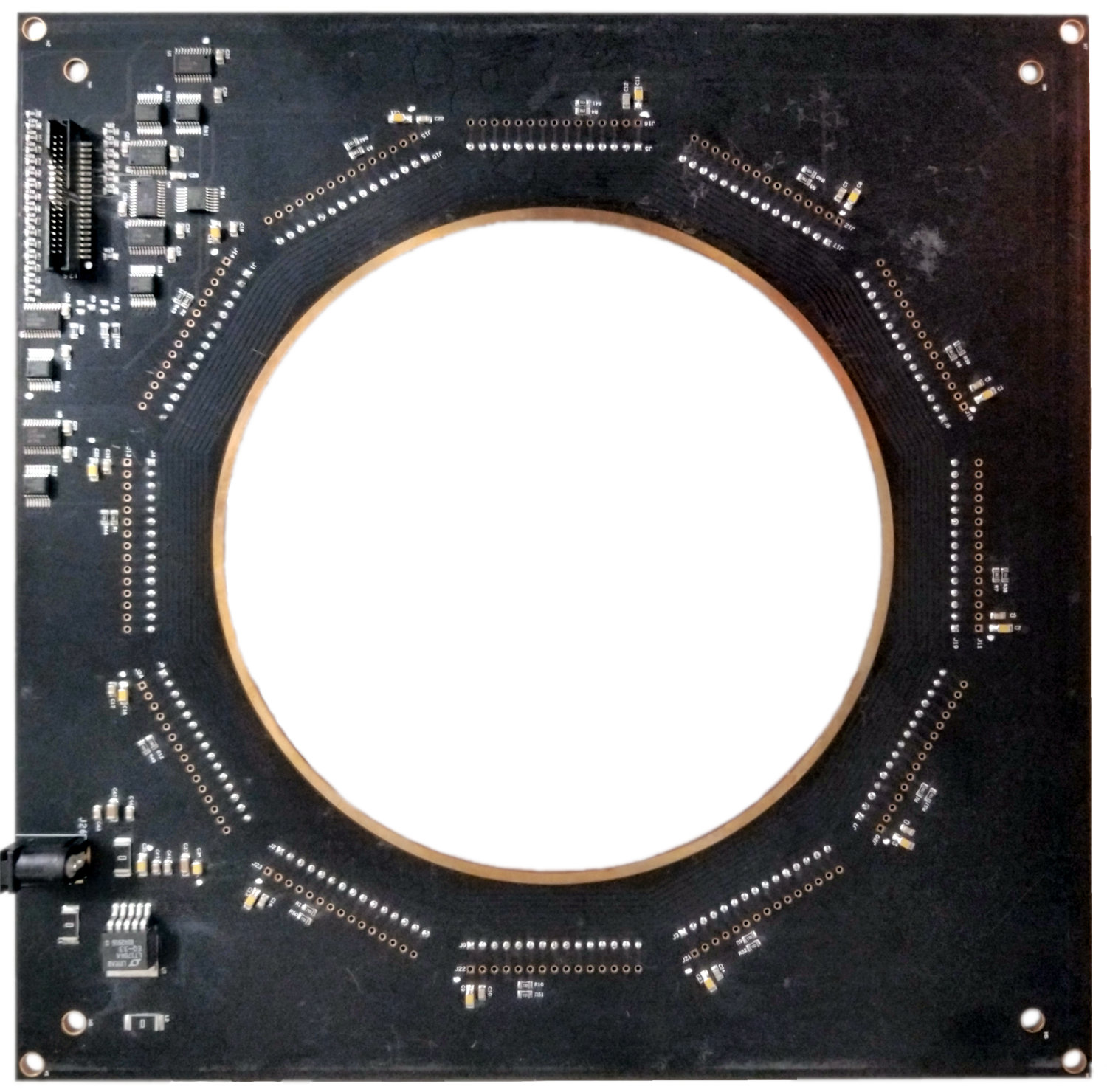
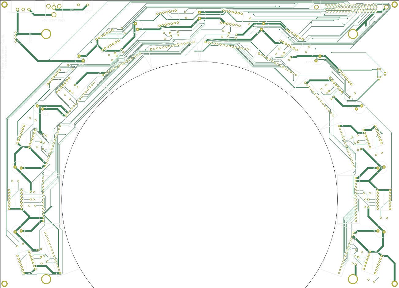
The Arena 12-12 Version 1 (OrCAD design file at arena_12-12/arena_12-12_v1.brd, see schematics) was developed in June 2017 as a 6-layer board. In addition to the connectors approximating an inner circle with 170mm diameter, it had a second row of connectors about 180mm apart. Another visible distinction is the eight vias inside the connector ring, which are used for the chip selects. The image on the right shows such an arena board with the ribbon connector on the top left and the power connector on the bottom left.
Arena 12-12 Version 2 (G4 LTS)
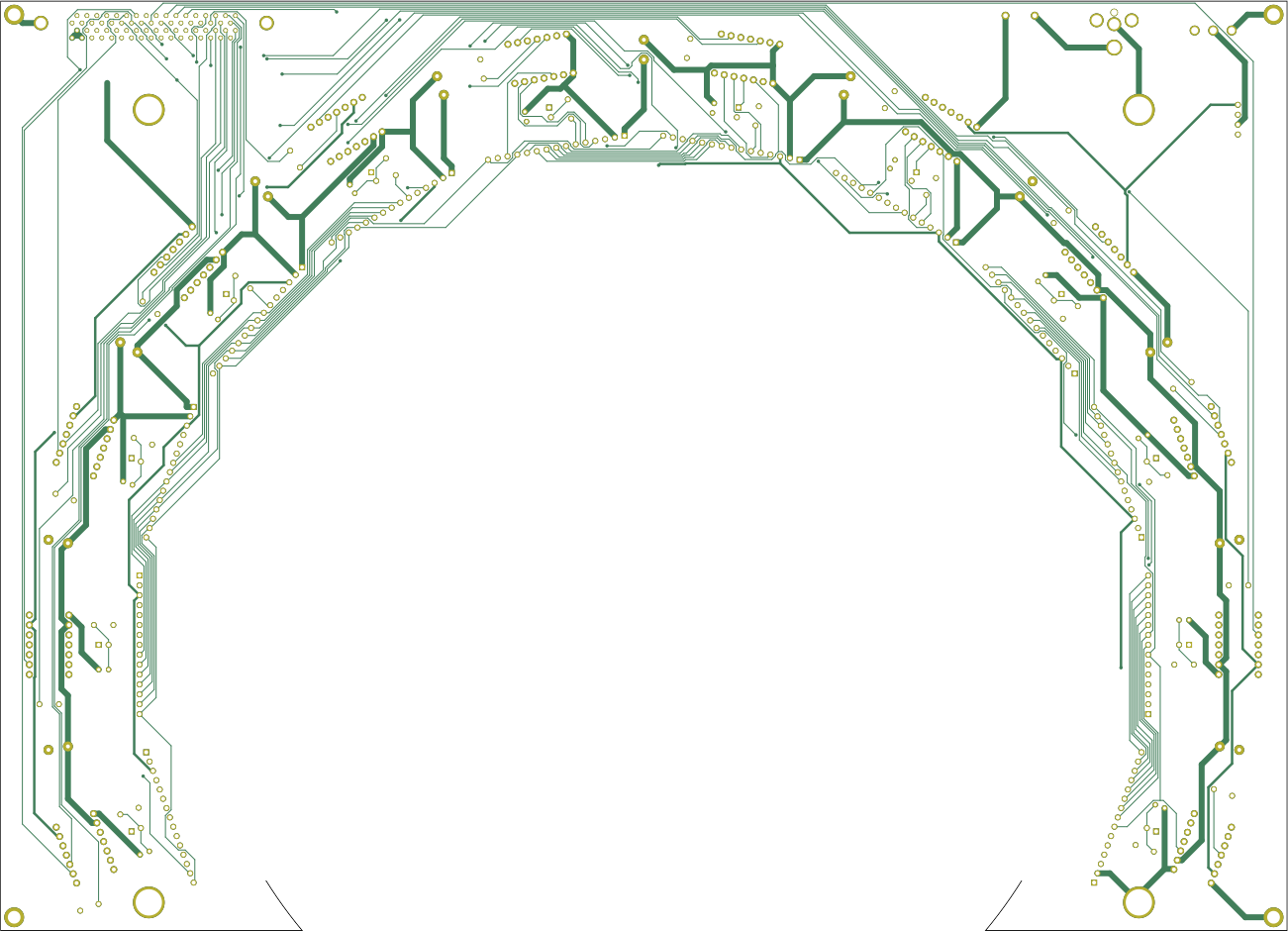
The Arena 12-12 Version 2 (OrCAD design file at arena_12-12/arena_12-12_v2.brd) is similar to version 1 in schematics and most of the pcb layout, but is missing the outer ring of potential connectors. Development on the 6-layer version 2 started in February 2018. If you want to repair a version 1 or version 2 board, we recommend the production files for Arena 12-12 v2.4 archived at arena_12-12/production_v2/arena_12-12_v2p4.zip as it includes incremental improvements like a more helpful silkscreen. Most of the arenas were hand-assembled using parts that our machine shop had on hand. Version v2.4 is an attempt to fill in some of the gaps and is a step towards being able to give the assembly job to an external contractor. Contact us about the progress if you have questions.
Arena 12-12 Version 2C (OrCAD design file at arena_12-12/arena_12-12_v2C) is a prototype to length match all signal lines and decrease electric noise by routing them on individual layers. As a result the board has 12 (hex: 0xC, hence 2C) layers. In our hands it didn’t show improvements over other version 2 boards, but if you are looking to debug timing issues this could be a helpful starting point.
Arena 12-12 Version 3 (G4 Prototype Double)
Arena 12-12 Version 3 (OrCAD design file at arena_12-12/arena_12-12_v3.brd, see schematics) is a 6-layer prototype with two rings of connectors and additional changes to the physical shape of the PCB. It never left prototyping stage and is here only for historical purposes. This version was designed in June 2019.
Arena 12-12 Version 4 (G4 LTS)
Arena 12-12 Version 4 (OrCAD design file at arena_12-12/arena_12-12_v4.brd, see schematics) is an attempt to further minimize noise in the system. To achieve that, the electronic design of this 6-layer PCB was changed in August 2019 so that the clock signal is now actively driven by a fanout instead of a simpler voltage translator as in previous versions. Furthermore, the chip select lines are isolated from each other through active components. The circular PCB was physically interrupted to avoid timing issues through circular traces.
Arena 12-12 Version 5 (G4 Prototype Direct)
The Arena 12-12 Version 5 (OrCAD design file at arena_12-12/arena_12-12_v5.brd, see schematics) is an experimental 6-layer design without an interconnect board but instead with a direct VHDCI connector. Development has been ongoing since Summer 2020, but the design does not work yet.
Arena 12-12 Version 6 (G4 Microscope Notch)
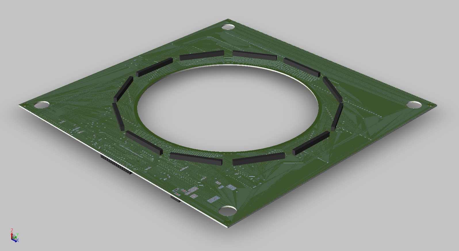
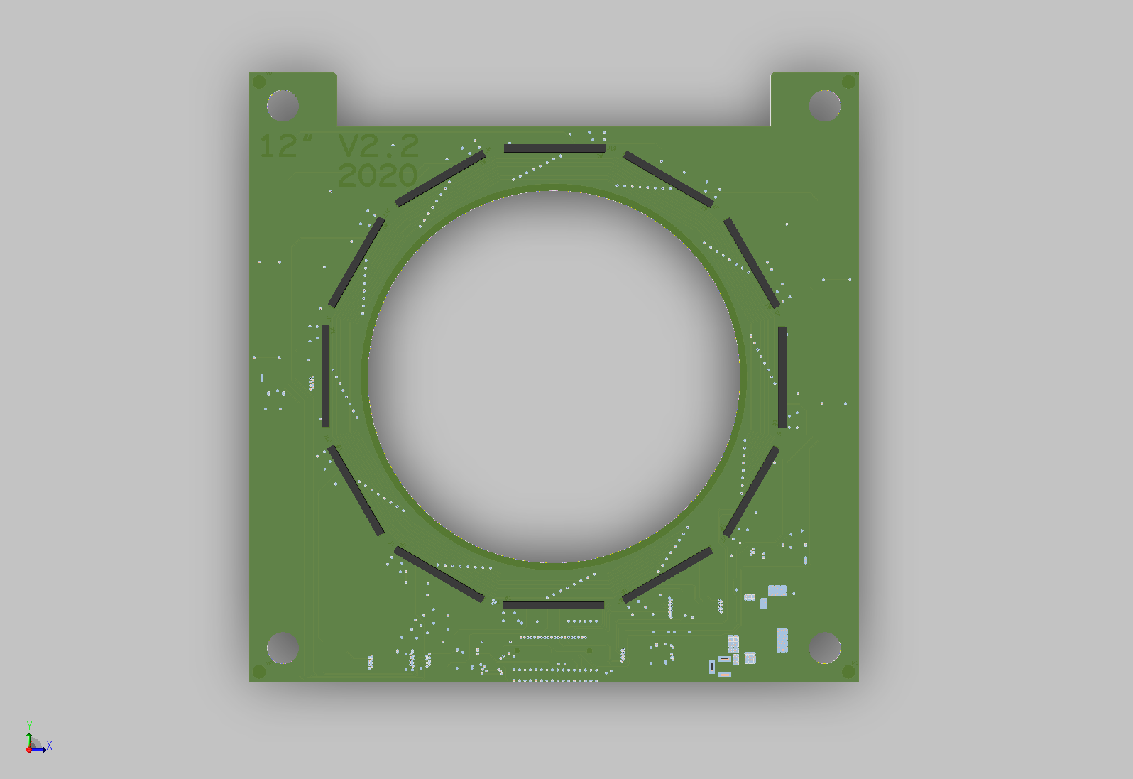
The Arena 12-12 Version 6 (OrCAD: arena_12-12/arena_12-12_v6.brd, schematic) is electrically the same as Version 2. The only difference is a notch (cutout) so the arena can slide under a specific microscope. Same schematic, same signals, same BOM (apart from mechanical mounting parts). Use production files at arena_12-12/production_v6/arena_12-12_v6p0.zip. It was first labeled v2.2, then renamed to v6.0 to avoid confusion with later v2.x updates.
Arena 12-12 Version 7 (G4.1 Prototype Power)
Arena 12-12 Version 7 (KiCad: arena_12-12/arena_12-12_v7_ni/arena_12-12_v7_ni.kicad_pro, schematics) is the first version with a dedicated top PCB (before this one board was used twice). It is also the point where active design moved into KiCad so the source files are openly available. Version 7 tried a higher-voltage distribution concept and local regulation on “comm” boards. We built a few units, but did not adopt this idea. Keep it for historical notes; do not choose it for a normal system.
Arena 12-12 Version 8 (G4.1 Prototype Inverted)
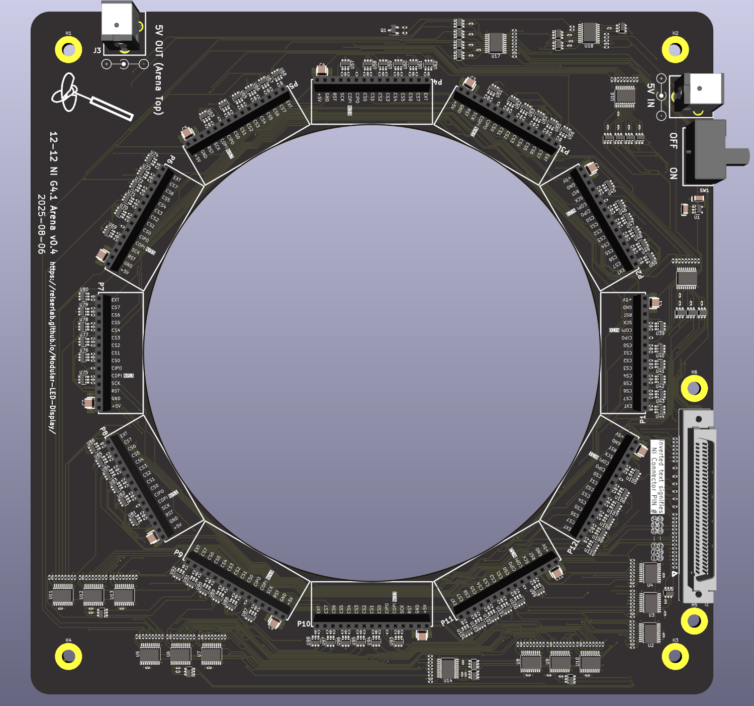
Arena 12-12 Version 8 (KiCad: arena_12-12/arena_12-12_v8_ni/arena_12-12_v8_ni.kicad_pro, schematics) is the first stable KiCad redesign that stays fully compatible with panel hardware from versions 1–6. Routing is cleaner (shorter power paths, clearer separation of signal and power), and silkscreen labels (pin 1 marks, polarity, column numbering) are easier to read. Early v8 boards had a column rotation / inversion issue; this was fixed, and v8.4 (silkscreen may show v0.4) is the recommended drop‑in if you need an intermediate KiCad build.
Arena 12-12 Version 9 (G4.1 Prototype Power)
Arena 12-12 Version 9 (KiCad: arena_12-12/arena_12-12_v9_teensy/arena_12-12_v9_teensy.kicad_pro, schematics) is a Teensy‑focused prototype again testing higher voltage and local regulation ideas. Iteration 2 improved physical placement for the Teensy. These boards are NOT electrically compatible with the normal Generation 4 panel interface (old or newer panel generations). Only use v9 if you are studying alternative power methods or doing exploratory firmware work. Otherwise move straight to v10.
Arena 12-12 Version 10 (G4.1 LTS)
Arena 12-12 Version 10 (KiCad: arena_12-12/arena_12-12_v10_teensy/arena_12-12_v10_teensy.kicad_pro, schematics) is a Teensy-focused version that is compatible with all Generation 4 panels (legacy and newer revisions). This is our development version for an inexpensive behavioral system.
Arena 12-12 Version 11 (G4.1 Top)
Arena 12-12 Version 11 (KiCad: arena_12-12/arena_12-12_v11_top/arena_12-12_v11_top.kicad_pro, schematics) is a dedicated top board that provides mechanical support and termination for the bottom boards. This version is recommended as the top board for any of the v7–v10 bottom boards when a top is needed. It features improved mechanical design and consistent connector placement.
Arena 12-12 Version 12 (G4.1 Top Belt)
Arena 12-12 Version 12 (KiCad: arena_12-12/arena_12-12_v12_belt/arena_12-12_v12_belt.kicad_pro, schematics) is a “belt” variant of the top board. This variant provides an alternative mechanical configuration while maintaining the same electrical interface and compatibility with v7–v10 bottom boards.
Top vs. Bottom PCB Split (v7+)
Versions 1–6 used one PCB twice: you built a “bottom” and a “top” by loading different BOM parts. Starting with version 7 there are TWO separate PCB layouts. The bottom board carries power distribution and main signal routing. The top board gives mechanical support, aligns the ring, and provides termination or extra connectors. Do not mix their roles; they are shaped and routed differently. When you modify or extend the design (extra sensors, new controller footprint), modify the silkscreen labels used in versions 8–10 so others can service the boards easily.
Open KiCad Source Availability
With the KiCad migration (initiated at v7), full schematic (.kicad_sch) and layout (.kicad_pcb) sources are openly accessible, enabling transparent modification, community contributions, forked experimental variants, and long-term archival. Users considering substantive changes (power filtering experiments, mounting variations, controller substitution) are encouraged to maintain consistent silkscreen conventions for maintainability and comparability across laboratories.
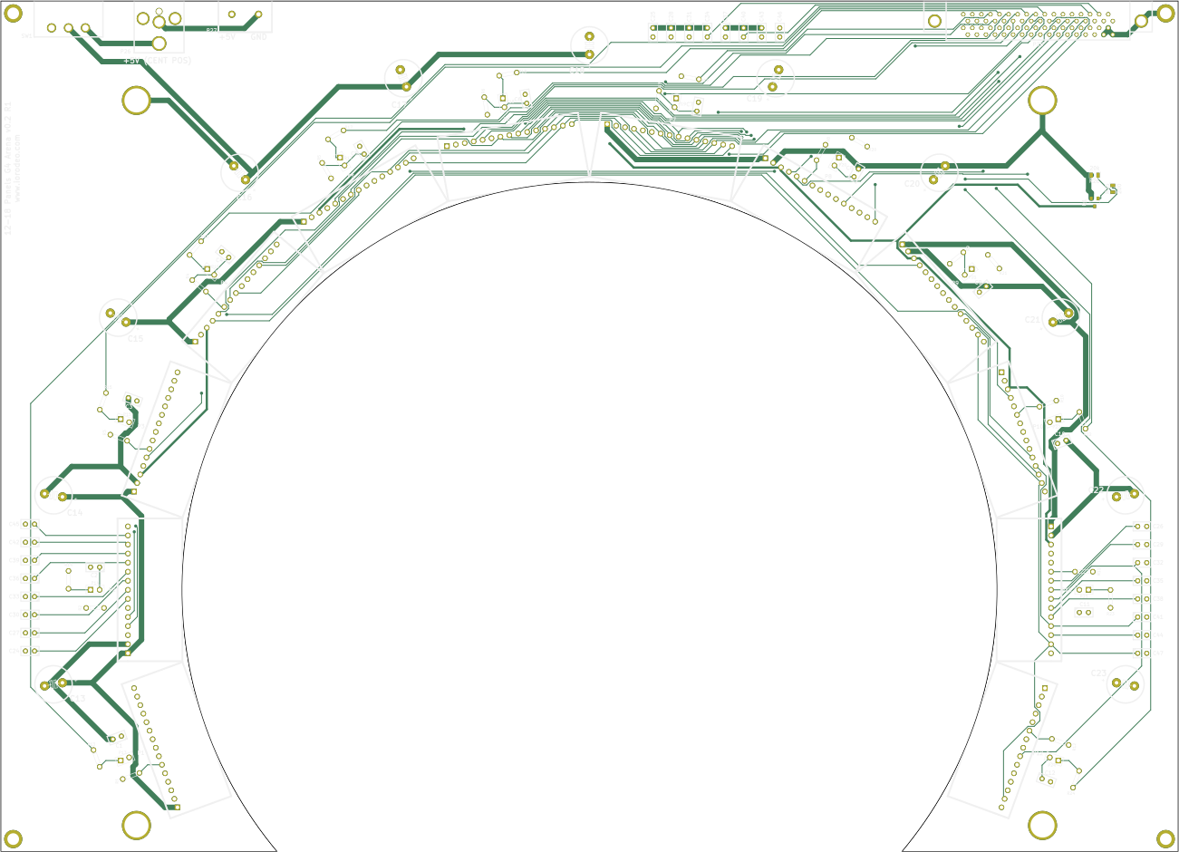
12-18 arena board
The Arena 12-18 populates 12 out of 18 sides of a regular octadecagon with panel connectors. This means the approximated cylinder can cover up to 240° of the visual field with a diameter of around 250mm. This type of arena is particularly useful for electrophysiology and imaging experiments.
Arena 12-18 Version 1 (G4 LTS)
Arena 12-18 Version 1 and 2 are based on the same schematic, differences are in routing. Also, Arena 12-18 v2.0 uses hidden vias, is more difficult and expensive to manufacture, and has not been used as often as boards from version 1 (and we cannot share the design files at present). Consequently, we recommend using the newest version 1 at the moment, archived at arena_12-18/production_v1/arena_12-18_v1p1.zip. The Arena 12-18 v1.1 is a 7-layer PCB with a footprint of 299×206mm². For a more detailed description and changelog, see the README.mdown file in arena_12-18/production_v1/.
Arena 12-18 Version 3 (G4 Acrylic Top)
 For some arenas, one board required a physical connection only, without an electrical one. In this case, a laser-cut board—for example, from acrylic—is sufficient. We share a file
 Arena_11-18_holder.svg in the arena_12-18 folder that can be used to laser-cut this type of board. See the local README.mdown file for further descriptions.
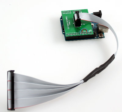
Arena Interconnect Board
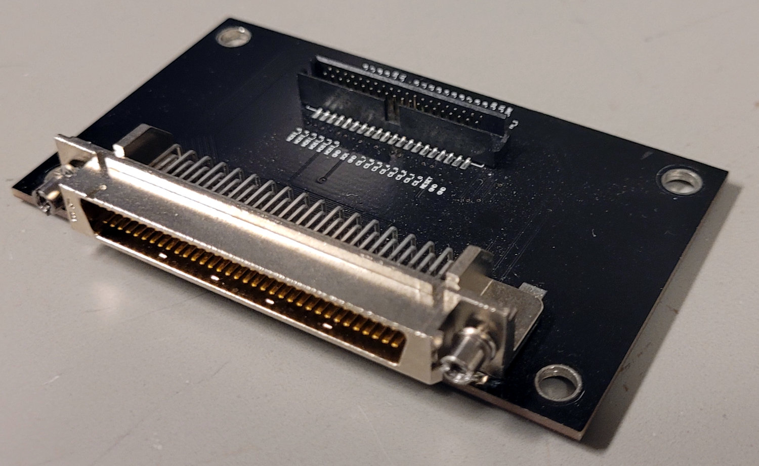
Some of the arenas are rotated during experiments and a direct connection of the stiff VHDCI cables would put unnecessary physical stress on the arena board and connector. Therefore the majority of arena boards use a 40pin header which can be used with flexible ribbon cables. The arena interconnect board acts as an adapter between a 40-pin arena connector and a 68-pin VHDCI connector from the computer PCIe card. Unfortunately, recent tests suggest that the ribbon cable introduces noise in the communication. The ribbon cable should be as short as possible to reduce the noise.
Arena Interconnect Board v1 (LTS)
The Arena Interconnect Board Version 1 (OrCAD design file at interconnect/interconnect_v1.brd, see schematics) is a simple 2-layer PCB with dimensions of 4.9×8.4mm². The most recent production files are archived at interconnect/production_v1/interconnect_v1p3.zip.
Arena Interconnect Board v2 (Prototype)
We also share the OrCAD design files (interconnect/interconnect_v2.brd) for an Interconnect Board Version 2 (see schematics). This board is designed as a 4-layer PCB with additional power connectors and a 15-pin connector. In theory, they could be used to drive a single column of panels directly. This design is currently untested and we recommend using version 1.
Arena Interconnect Board v3 (Prototype)
There are the beginnings of an idea for a version 3, sketched in KiCAD. It still needs routing, but if there is a need to fix something on the interconnect board, this might be an easier route than trying to recover v1 or v2.
Historic
These files were found in shared drives and previous conversations, but the intent, production state, and uses are mostly unknown. We mention and share the files in case someone finds a setup based on it, but don’t recommend using any of them.
Imaging setups
12-18 arena board v0.2
The initial version of a 12-18 arena was designed in KiCad (see schematic and pcb), but the production never exceeded the version 0.2. The project is at arena_12-18_v0.
12-18 arena board v0.1
Early on, a 12-18 arena called with shifters was designed in KiCad (see project at arena_12-18_s_v0 and schematic), but production in arena_12-18_s_v0/production_v0 never exceeded version 0.1.
Prototype arenas
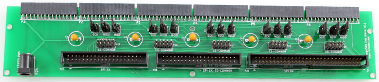
6 connector arena prototype (6-inf arena)
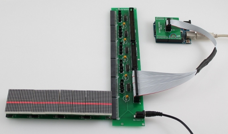
The test arena with 6 panel connectors in a row (called a 6-inf arena) is used to connect the panels with the controller and to supply power to the panels. There are three different headers that can be used to connect the panels to the display controller.
- P22 40-Pin (2x20) single SPI bus header.
- P23 60-Pin (2x30) six SPI bus header.
- P30 40-Pin (2x20) six SPI bus w/ common chip select lines.
5V power is supplied to the panels via a 2.1mm DC jack, polarity is center positive.
There are three different versions for the ATmega328-based panels, one for the MAX6960 panels.
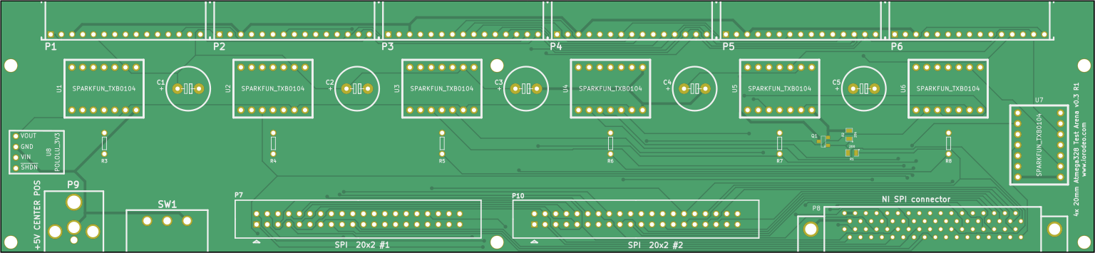
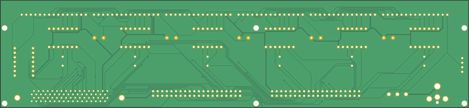
Design files for version 0.3 of the 6-inf arenas for an ATmega328 (see schematic) are available in arena_6-inf_v0p3, production files in the subfolder arena_6-inf_v0p3/production_v0.
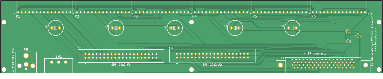
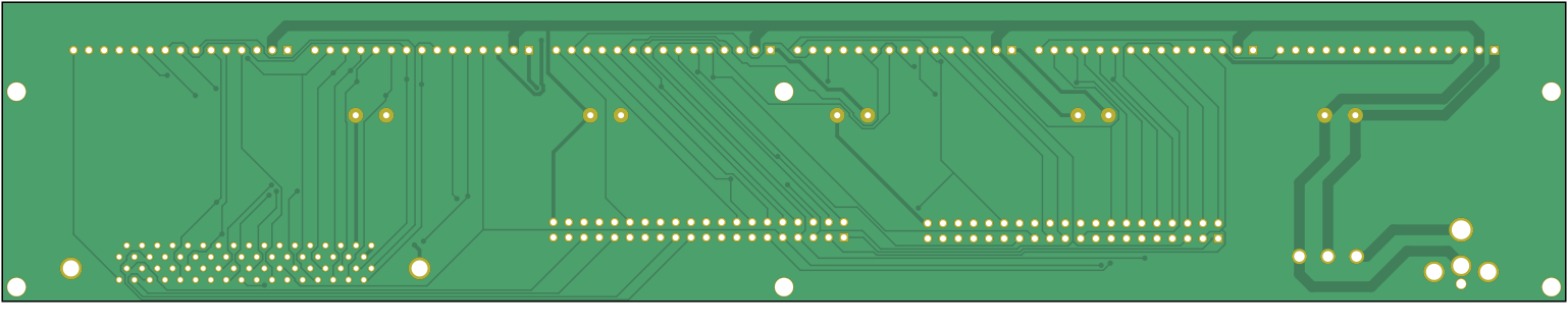
Design files for version 0.2 of the 6-inf arenas for an ATmega328 (see schematic) are available in arena_6-inf_v0p2, production files in the subfolder arena_6-inf_v0p2/production_v0.
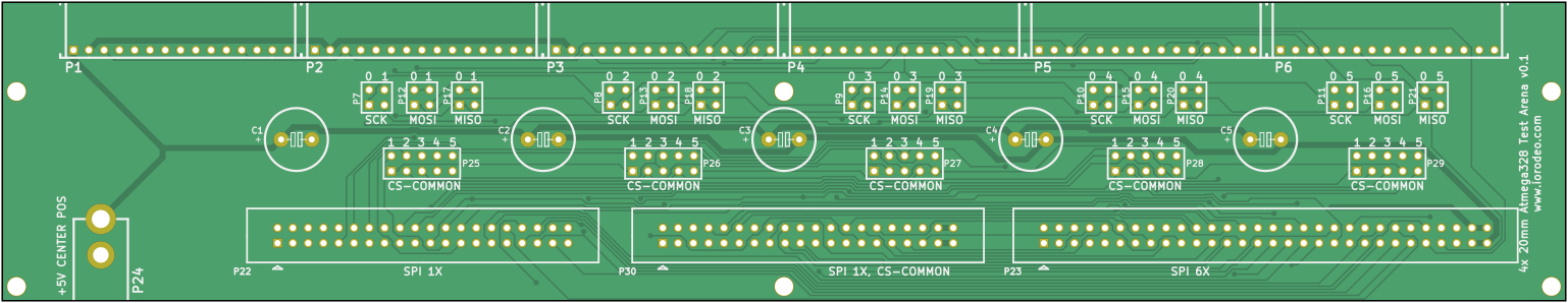
Design files for version 0.1 of the 6-inf arenas for an ATmega328 (see schematic) are available in arena_6-inf_v0p1, production files in the subfolder arena_6-inf_v0p1/production_v0. There are 5 sets of jumpers which can be used to configure the arena.
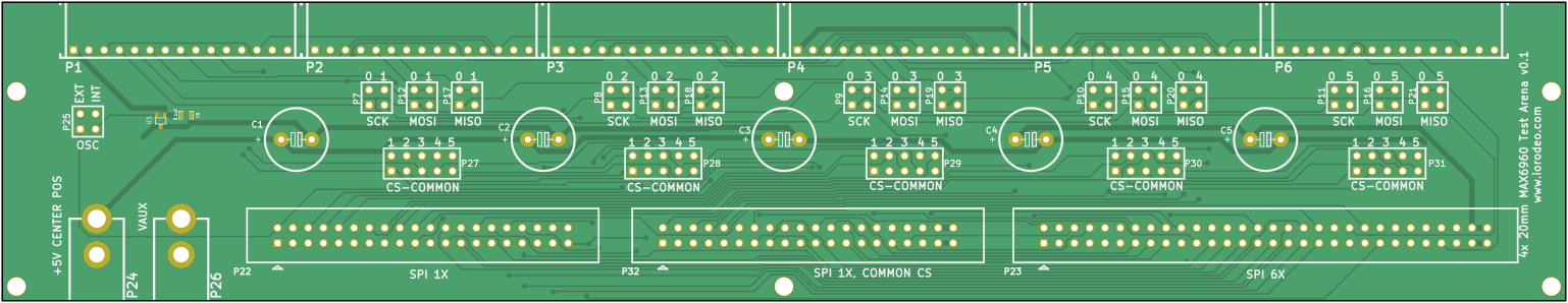
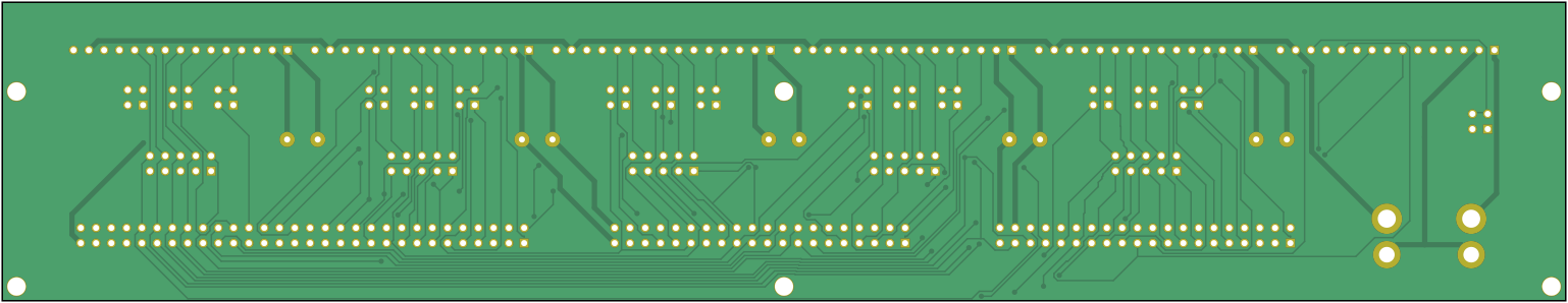
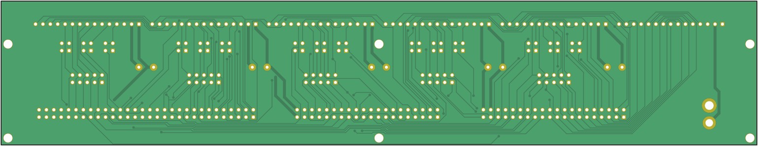
There is also a 6-inf arena for a MAX6960 driver (see schematic) available in arena_6-inf_max6960. This specific one only made it to version 0.1; production files are in the subfolder arena_6-inf_max6960/production_v0.
Development
There are currently a few arenas in development. We will describe them in more detail once we have characterized them further. Currently, we call them G4.1: they are compatible with the previous systems, but solve some of the issues we faced with the Generation 4 arenas.
Prototype Controller
A demonstration controller, based on an Arduino Uno, is provided with the arena and panels. The demonstration controller connects to header P22 on the arena and will display a moving stripe pattern in 16-level grayscale mode. The panels (up to four) should be connected to header P1 when using the demo controller. Note that the demo controller requires 5V power via the USB connector on the Arduino Uno in order to operate.
The firmware for an Arduino Uno, Arduino Due, and Teensy 3 is in the Firmware repository. We cannot find the shields to connect these boards to the test arena at the moment, but they should be fairly easy to reverse engineer. But then again, we cannot think of a use case for the prototype controller or the prototype arena.