BNC Breakout


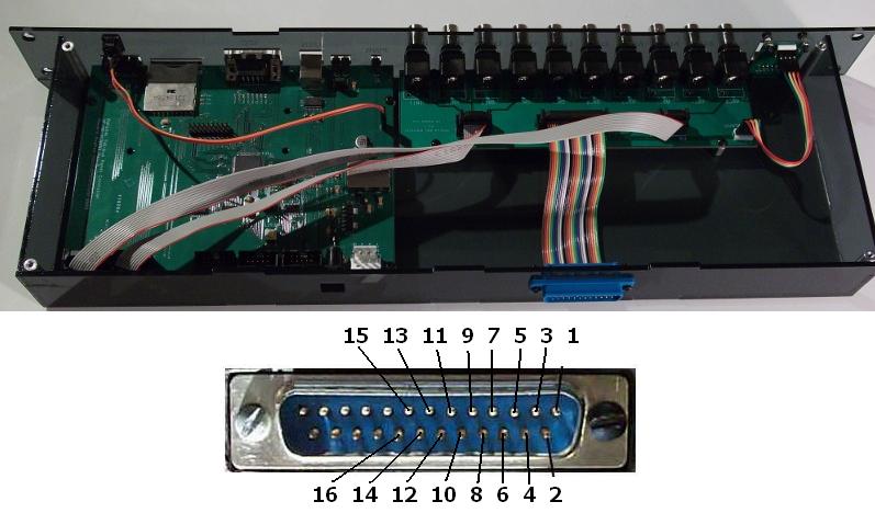
This is an additional PCB for the Controller which adds 10 BNC connections to the Controller. Have a look at the preview of the schematics.
Connections

The rear breakout connection of the BNC controller can be used to directly access the following signals:
| signal | 26pin header | 25pin D-sub (rear connector) |
|---|---|---|
| 5V | 1 | 13 |
| GND | 2 | 25 |
| ADC0 | 3 | 12 |
| ADC1 | 4 | 24 |
| ADC2 | 5 | 11 |
| ADC3 | 6 | 23 |
| ADC4 | 7 | 10 |
| ADC5 | 8 | 22 |
| DAC0 | 9 | 9 |
| DAC1 | 10 | 21 |
| DAC2 | 11 | 8 |
| DAC3 | 12 | 20 |
| INT0 | 13 | 7 |
| INT1 | 14 | 19 |
| INT2 | 15 | 6 |
| INT3 | 16 | 18 |