Treadmill Illumination PCB
 → to GitHub project folder
A two-channel LED driver board for near-infrared (NIR) illumination of the spherical treadmill in the “Integrated Inexpensive Treadmill”. The current version 2 runs from a regulated 5 V supply and drives two 850 nm LEDs in series per channel, with a trimmer per channel for brightness. The circuit contains no ICs and no PWM: brightness is set resistively, which keeps assembly simple and the adjustment stable between sessions. The earlier 12 V version 1 is described further down.
Version 2 (5 V)
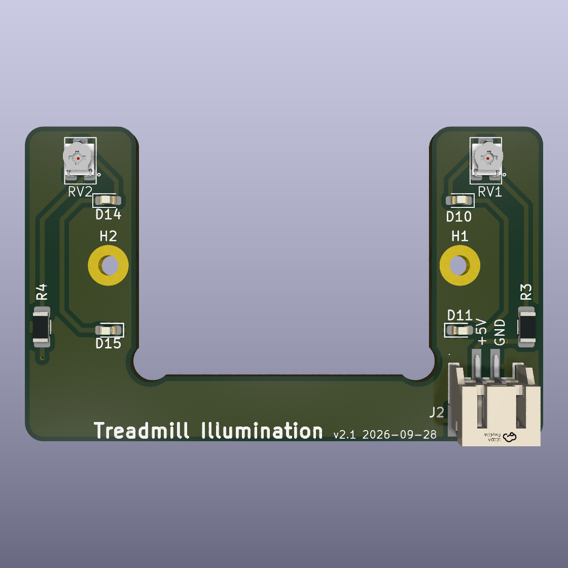
The v2 board in Treadmill-Illumination-v2-0603-smd/ is powered through J2, a polarized right-angle (side-entry) SMD JST PH connector at the bottom edge; the cable leaves in the plane of the board instead of standing up from it. All parts are surface-mount on the top side. Each of the two independent channels is a chain of +5 V → fixed resistor → trimmer → LED → LED → GND. This is the 0603 LED alternate; the 1206 LED alternate is in Treadmill-Illumination-v2-1206-smd/, and a through-hole alternate in Treadmill-Illumination-v2-tht/ is described below.
The trimmer is wired as a variable resistor (rheostat): its wiper and one end terminal are tied together, so a wiper that loses contact leaves the full track in circuit, and the LEDs dim instead of going bright. Two trimmers let the two sides be balanced against each other at the ball, compensating for LED-to-LED output spread and lamp placement. Two M2 mounting holes (H1, H2) are plated and connected to GND.
| Reference | Component | Value | Part (LCSC) |
|---|---|---|---|
| J2 | JST PH 2-pin, right-angle SMD, 2 mounting tabs (to GND) | pin 1 +5 V, pin 2 GND | JST S2B-PH-SM4-TB(LF)(SN) (C295747) |
| R3, R4 | Resistor, 1206 SMD, thick film ±1%, ±100 ppm/°C, ¼ W at 70 °C | 110 Ω | FOJAN FRC1206F1100TS (C2933579) |
| RV1, RV2 | Trimmer potentiometer, single-turn, SMD | 100 Ω | JIERR JER33X-1-12 (C52033642) |
| D10, D11, D14, D15 | NIR LED 850 nm, 0603, 120° | 2 per channel | Xinglight XL-1608HIRC-850 (C965885) |
Operating limits
- Supply: regulated 5.0–5.25 V, for example a USB power adapter. Never connect a 12 V supply (such as a v1 cable): the LEDs are overdriven and the resistors overheat. The input has no reverse-polarity protection.
- Ambient temperature up to 30 °C. The LED’s maximum current falls with temperature (30 mA at 25 °C, about 27.5 mA at 30 °C). Using the datasheet’s 25 °C forward-voltage limits, no combination of parts and supply exceeds that (at most 26.2 mA). The datasheet gives no forward-voltage limits at 30 °C, so confirm on the rig by measuring current at 5.25 V after warm-up (see the bench test). “Ambient” means the air temperature next to the LEDs, including any heat from the rig.
- Flicker: there is no PWM, but brightness follows the supply. As a guide, 50 mV of supply ripple changes brightness by about 2%.
Expected LED current per channel. These are estimates from a diode model fitted to the datasheet; the 26.2 mA bound uses only the datasheet’s minimum forward voltage.
| Trimmer at minimum (brightest) | Trimmer at maximum (dimmest) | |
|---|---|---|
| Typical board (Vf 1.5 V, 5.0 V supply) | 18.4 mA | 10.3 mA |
| Weakest board (Vf 1.7 V, 4.75 V supply) | 13.2 mA | — |
| Strongest board (Vf 1.2 V, 5.25 V supply) | 25.4 mA, at most 26.2 mA | — |
Light output scales roughly linearly with current. At the strongest-board worst case, each resistor dissipates at most 75 mW (rated 250 mW) and each LED at most about 37 mW (rated 45 mW at 25 °C). The trimmer carries the full LED current near its bright end; for a 100 Ω, 0.15 W part used as a rheostat, the usual limit is √(P/R), about 35 mA even at the trimmer’s +25% tolerance, so there is ample margin. The design trades adjustment range for this safety margin: the trimmer covers roughly 1.7–1.8:1 in current. That trims brightness and usually balances the two sides, but LED output varies by up to 10× between bins, so check the balance in the camera. If one side stays too bright even at the dim end, raise that side’s fixed resistor (for example to 130 or 150 Ω). For much dimmer light overall, reduce the camera exposure.
Assembly notes
- LED polarity. The XL-1608HIRC-850 marks the anode, the opposite of most LEDs: the green mark is on its anode end. On the board, the silkscreen bracket around each LED is closed on the cathode side (pad 1). Place each LED with its mark at the open end of the bracket. A reversed LED leaves that channel dark. Check one LED with a multimeter diode test before soldering the rest.
- Mounting. Because H1 and H2 are connected to GND, metal screws into a grounded metal frame connect the LED supply ground to the rig ground. Use a plastic mount or nylon screws if that matters for the setup.
- Cable. Use a JST PHR-2 housing (LCSC C157955) with SPH-002T-P0.5S crimp contacts (C111515, 24–30 AWG, insulation 0.9–1.5 mm), or a pre-crimped 2-pin PH lead. Pre-made PH leads, for example those sold for LiPo batteries, do not follow a consistent color or polarity convention. Before connecting, check that the positive wire lands on pin 1, the pin marked +5V. J2 is a surface-mount part held by its two contact joints and two mounting tabs; tie the cable to the mount instead of letting it hang from the connector.
Bring-up and bench test
Measure LED current as the voltage across the 110 Ω resistor: 1 V ≈ 9.1 mA. Probe the two end caps of the 1206 resistor.
Before power-up:
- No short between +5 V and GND at J2.
- The resistance from each trimmer’s pin 1 to its wiper spans from about 0 Ω to 75–125 Ω as you turn it (the trimmer’s ±25% tolerance).
- With the cable plugged into the supply but not into the board, check that the wire going to pin 1 is positive.
Powered from the regulated 5 V supply, with both trimmers first turned to the dim end:
| Check | Expected | Stop if |
|---|---|---|
| Voltage across R3/R4, trimmer at the dim end | about 1.1 V (10 mA) | — |
| Same, trimmer at the bright end | about 2.0 V (18 mA), up to 2.8 V with low-Vf LEDs | above 2.9 V (26.4 mA): wrong resistor, wrong trimmer, a shorted or bridged LED, or supply above 5.25 V |
| Brightness changes smoothly over the whole rotation | yes | a large dead zone (suggests a wiring error) |
| A channel is dark | — | check LED orientation |
Balance the two channels by looking at the ball in the tracking camera, not by matching currents. The LEDs vary in output by up to 10× between bins at the same current, so equal currents do not mean equal brightness. Note which direction of rotation is brighter.
If a board is too dim for tracking (for example with high-Vf LEDs), R3/R4 can be swapped for 100 Ω or 91 Ω 1206 resistors. Do this only on a board you have measured, and check it under worst-case conditions: supply set to 5.25 V at J2, board warmed up for 10 minutes on the rig at or below 30 °C, trimmer at the bright end. The voltage across the new resistor must stay below 2.475 V for 100 Ω or 2.25 V for 91 Ω (25 mA, allowing for the resistor’s 1% tolerance). If you can only test at 5.0 V, don’t swap: a board that passes at 5.0 V can exceed the limit at 5.25 V. For boards built by others, keep 110 Ω.
Through-hole alternate
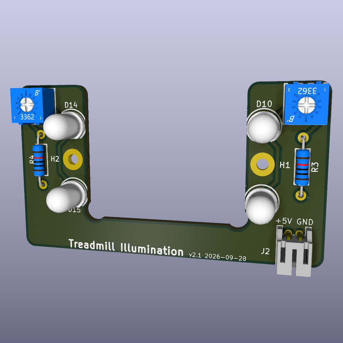
Treadmill-Illumination-v2-tht/ builds the same circuit from through-hole parts, for hand assembly. The sections above describe the surface-mount alternates; this section covers what differs. The channel chain, the rheostat wiring of the trimmers and the GND-connected mounting holes are unchanged, and the LEDs sit at the same positions around H1 and H2.
To fit the larger trimmers, the outer edge of each arm is 2.5 mm further out, so the board is 61 × 34 mm instead of 56 × 34 mm. The mounting holes and the inner cutout are in the same places. J2 sits 3.2 mm further right than on the surface-mount boards. The LEDs stand about 8.7 mm above the board and the trimmers about 5 mm, so check the clearance on the rig.
| Reference | Component | Value | Part (LCSC) |
|---|---|---|---|
| J2 | JST PH 2-pin, right-angle THT | pin 1 +5 V, pin 2 GND | JST S2B-PH-K-S-GW (C157932) |
| R3, R4 | Resistor, axial THT, metal film ±1%, ±50 ppm/°C, 0.6 W at 70 °C, 10.5 mm pitch | 110 Ω | Vishay MBB02070C1100FCT00 (C1365973) |
| RV1, RV2 | Trimmer potentiometer, single-turn, top adjust, THT, ±10%, 0.5 W | 200 Ω | JIERR 3362P-1-201LF (C48997948); Bourns 3362P-1-201LF (C124581) fits the same footprint |
| D10, D11, D14, D15 | NIR LED 850 nm, 5 mm THT, 30°, 2.54 mm lead spacing | 2 per channel | Everlight HIR8323/C16 (C367225) |
Operating limits (through-hole)
- Supply: the same as above: regulated 5.0–5.25 V, never 12 V, and no reverse-polarity protection.
- Ambient temperature up to 30 °C. The HIR8323/C16 is rated 100 mA at 25 °C, derating to about 90 mA at 30 °C, and 150 mW (about 135 mW at 30 °C). Even with both LEDs of a channel shorted, R3/R4 limit the current to 48 mA, so no combination of parts and supply can overdrive the LEDs. Unlike the surface-mount boards, this does not depend on the LEDs’ forward voltage, for which the datasheet gives no minimum.
- Flicker: as above, 50 mV of supply ripple changes brightness by about 2%.
Expected LED current per channel at 30 °C. These are estimates from a diode model fitted to the datasheet, including the LEDs’ self-heating. The datasheet gives only typical and maximum forward voltage; the 1.2 V strongest case is an assumption, and the shorted-LED row bounds it.
| Trimmer at minimum (brightest) | Trimmer at maximum (dimmest) | |
|---|---|---|
| Typical board (Vf 1.45 V at 20 mA, 5.0 V supply) | 19.7 mA | 7.5 mA |
| Weakest board (Vf 1.65 V at 20 mA, 4.75 V supply) | 14.6 mA | 5.6 mA |
| Strongest board (Vf 1.2 V at 20 mA, 5.25 V supply) | 26.1 mA | — |
| Both LEDs shorted (fault), 5.25 V supply | 48 mA | — |
In the strongest-board case, each resistor dissipates about 75 mW (rated 600 mW) and each LED about 31 mW. Used as a rheostat, the 200 Ω, 0.5 W trimmer handles about √(P/R) ≈ 53 mA even at its −10% tolerance, above the shorted-LED fault current. The trimmer covers about 2.6:1 in current. The HIR8323/C16 is sold in radiant-intensity bins of 20–30 and 25–50 mW/sr at 20 mA, so LEDs differ by up to 2.5× and the trimmer range covers that spread; still balance the two sides in the camera. The 30° beam is much narrower than the 120° of the surface-mount LEDs: it puts more light on the ball at the same current, but the spot depends on how straight the LEDs stand.
Assembly notes (through-hole)
- LED polarity. The HIR8323/C16 follows the usual convention: the flat on its flange marks the cathode. Each LED’s silkscreen outline has a matching flat on the cathode side (pad 1), facing the bottom edge of the board. Match the flats. A reversed LED leaves that channel dark. Check one LED with a multimeter diode test before soldering the rest.
- LED aim. Seat each LED with its flange flat on the board before soldering. With a 30° beam, a tilted LED visibly moves the spot on the ball. The LED leads are intentionally oriented vertically so the user can bend the pins to direct the beam toward the ball, as desired.
- Mounting and cable. The mounting note above applies unchanged. J2 mates with the same PHR-2 housing and SPH-002T-P0.5S contacts; it is held only by its two soldered pins, so tie the cable to the mount.
Bring-up and bench test (through-hole)
Follow the procedure above with these values. Current is still measured as the voltage across the 110 Ω resistor, 1 V ≈ 9.1 mA; probe the two leads of R3/R4. Before power-up, the resistance from each trimmer’s pin 1 to its wiper should span from about 0 Ω to 180–220 Ω (the trimmer’s ±10% tolerance).
| Check | Expected | Stop if |
|---|---|---|
| Voltage across R3/R4, trimmer at the dim end | about 0.8 V (7.5 mA) | — |
| Same, trimmer at the bright end | about 2.2 V (20 mA), 1.6–2.9 V across the LED spread | above 3.0 V (27 mA): wrong resistor, wrong trimmer, a shorted or bridged LED, or supply above 5.25 V |
The remaining checks (smooth adjustment, dark channel) and balancing by camera are the same as above.
If a board is too dim for tracking, R3/R4 can be swapped for 100 Ω or 91 Ω axial resistors. The strongest board then reaches about 29 or 31 mA, and even a shorted LED pair stays at 53 or 58 mA, below the LEDs’ 90 mA rating, so no worst-case bench test is needed. With 91 Ω, however, a shorted-LED fault would exceed the trimmer’s rheostat rating, so prefer 100 Ω. The 3.0 V stop limit above still applies.
Version 1 (12 V, legacy)
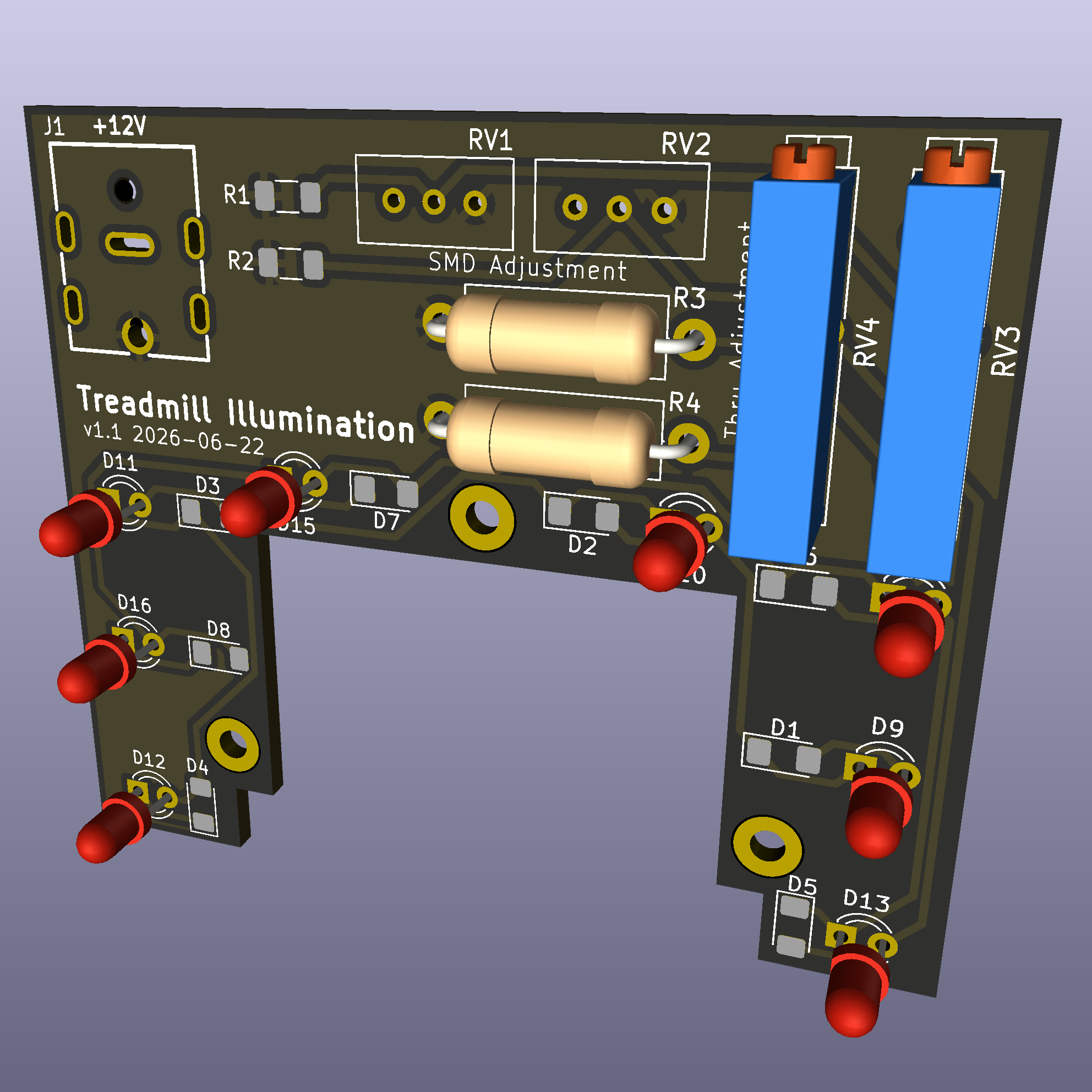
12 V DC enters through a barrel jack. Each of the two independent channels connects a trimmer and a current-limiting resistor in series with four NIR LEDs. Adjusting the trimmer changes the effective resistance in the chain and therefore the LED current and brightness. Because the two channels share only the supply, each lamp cluster can be set independently. Three M2 mounting holes allow the board to be attached to the newest iteration of the integrated inexpensive treadmill.
Bill of materials (v1.1 THT build)
| Reference | Component | Value |
|---|---|---|
| J1 | DC barrel jack | 5.5/2.1 mm THT |
| D9–D16 | NIR LED, 3 mm THT | 4 per channel |
| R3, R4 | Resistor, axial THT | 120 Ω |
| RV3, RV4 | Trimmer potentiometer | Bourns 3005, 25 turns |
SMD alternative (DNP in v1.1)
The PCB also carries footprints for a surface-mount build. In v1.1 these are marked DNP (do not populate). Do not populate both variants on the same channel.
| Reference | Component | Notes |
|---|---|---|
| D1–D8 | NIR LED, 1206 SMD | 4 per channel |
| R1, R2 | Resistor, 0805 SMD | 1 kΩ |
| RV1, RV2 | Trimmer | Bourns 3386C, single-turn: coarse adjustment |
Production files
Treadmill-Illumination-v2-0603-smd/production/ contains the fabrication package for the 0603 LED alternate of version 2: a Gerber/drill ZIP and IPC netlist, formatted for JLCPCB. The 3D model of the assembled board is Treadmill-Illumination-v2-0603-smd/assets/Treadmill-Illumination-v2-0603-v2.1.step. Treadmill-Illumination-v2-1206-smd/production/ contains the same package for the 1206 LED alternate, with 3D model Treadmill-Illumination-v2-1206-smd/assets/Treadmill-Illumination-v2-1206-v2.1.step.
Treadmill-Illumination-v2-tht/production/ contains the same package for the through-hole alternate, with 3D model Treadmill-Illumination-v2-tht/assets/Treadmill-Illumination-v2-tht-v2.1.step.
The v2 projects share the custom KiCad libraries in libraries/, with symbols, footprints, and 3D models from the EasyEDA/LCSC library. The surface-mount alternates use the JST connector (LCSC C295747) and the trimmer (LCSC C48997897); the through-hole alternate uses the JST connector (C157932), the LED (C367225), the resistor (C1365973) and the trimmer (C48997948). The pads of the EasyEDA LED footprint are renumbered to KiCad’s LED convention (pad 1 = cathode, at the flat) so they match the Device:LED symbol, and the through-hole trimmer’s 3D model is offset by 1.12 mm to sit on its footprint. KiCad finds the libraries through a path relative to each project, so keep libraries/ next to the v2 project folders when copying them.
Treadmill-Illumination-v1/production/v1.1/ contains the legacy version 1.1 package (Gerber ZIP and IPC netlist), ordered from project “Treadmill Illumination” as W2026062323003684 on 2026-06-23. Treadmill-Illumination-v1/production/v1.0/ contains the earlier revision with a panel ZIP and IPC netlist only. The 3D model of the assembled v1.1 board is Treadmill-Illumination-v1/assets/Treadmill-Illumination-v1.1.step.