Fly Pyramid: A reference of the parametrically designed fly holder

Introduction
This version of the fly holder is meant to be printed with a resin printer with the provided model supports. This edition of the fly pyramid is optimized for a wide range of customizability and parameterization for resin 3d printing. Drosophila, microscopes, and mounting equipment vary in size and shape, and will often cause necessary changes in the fly holder design.
The current model of the Fly Pyramid was designed in a free, open source 3d modeling software called FreeCAD, which is available for all major platforms (Linux, Windows, and Mac). This design was created in FreeCAD version 0.21.2, and made in the weekly version of FreeCAD. To properly parameterize the model, any latest weekly version after version “38314” will work. However, due to unknown complications, the final version of the model only works in Windows.
Altering these parameters, which are explained and documented in this reference, allows for a large range of fly holders to be customized. To alter the designs, the FreeCAD software will need to be installed, where a list of parameters will be shown on a spreadsheet. Furthermore, a tutorial to print the model and the best settings are shown at the end of the document. The FreeCAD file (.FCstd), which can be used to parameterize the model, cannot be directly imported into a slicer model. Instead, the FreeCAD model needs to be exported either as an OBJ or as an STL, which will be shown at the end of the document. Furthermore, the default OBJ and STL files, which cannot be parameterized and include only default settings, are also linked in the GitHub below. Both the OBJ and STL files, however, can be directly imported into a slicer to be 3d-printed. In general, stl files were used. However, in rare cases, the preferable STL format led to erroneous rendering in the Lychee slicer software. Switching to the OBJ file format solved this problem. In GitHub, both formats are provided to work around similar issues.
Overview
The following documentation describes the parameters and customization of the Fly Pyramid Model for application in various experiments. To change the following parameters, open the FreeCAD file and click on Fly Pyramid Parameters near the top left. This will open a spreadsheet with a list of parameters and values as shown below. Values on a yellow background can be modified, red parameters are “read only” references that are calculated by the model and based on the modified parameters.
The Fly Pyramid Design and its parameters will be grouped into the following sections to make the documentation and labeling easier to follow. The image below displays the sections and names of each.
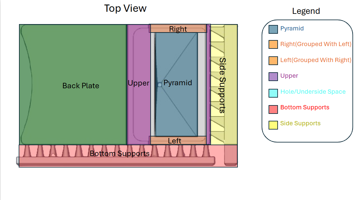
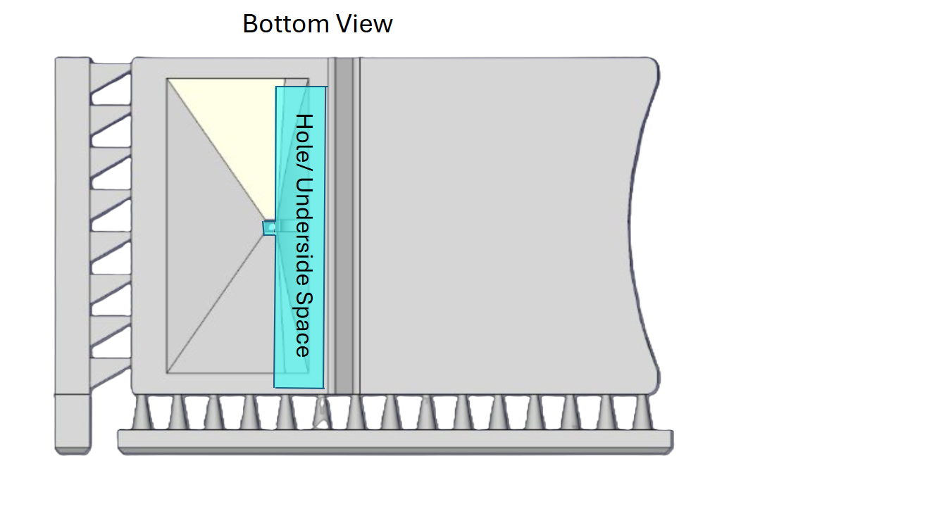 Figure 1: **(a) Pyramid overview (top)** Naming scheme used in this documentation for the component of the pyramid as seen from the top. **(b) Pyramid overview (bottom)** Component name as seen from the bottom.
 Pyramid
 (a) RectLength (Section 2.1.1)
 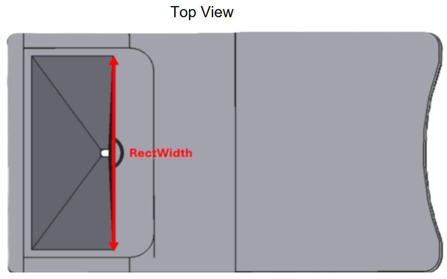 (b) RectWidth (Section 2.1.2)
 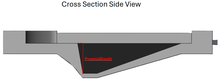 (c) PyramidDepth (Section 2.1.3)
 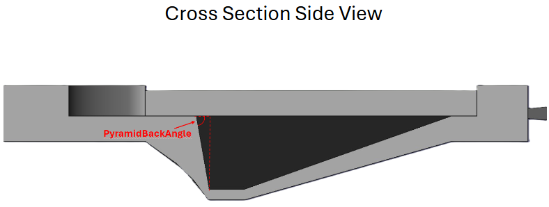 (d) PyramidBackAngle (Section 2.1.4)
 RectLength
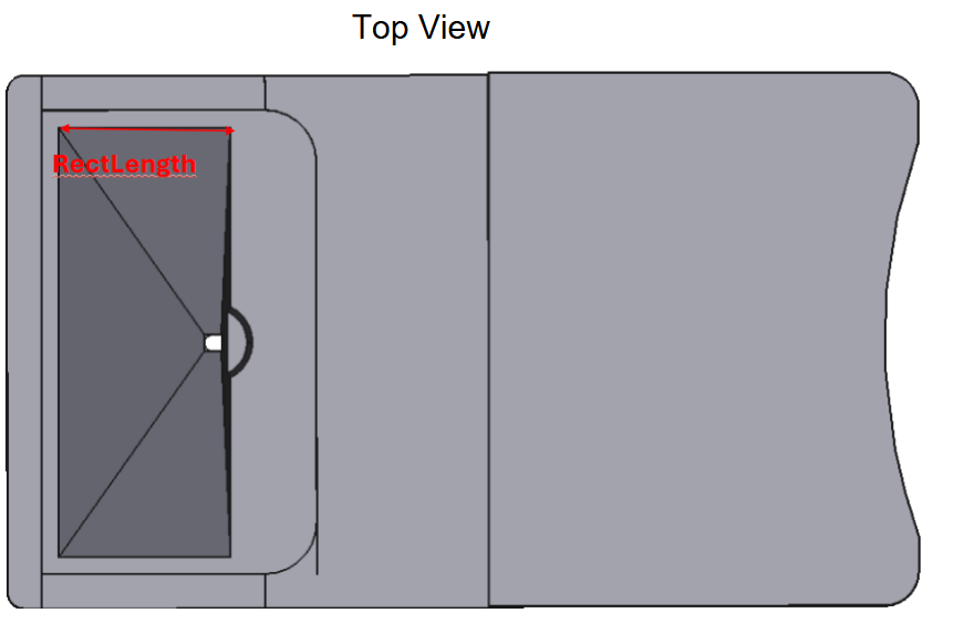
RectLength (default: 10mm) describes the distance between the beginning of the indentation that is shaped like a pyramid to the end of this indentation (see Figure 2 (a)).
This parameter is closely associated with the RectWidth parameter (Section 2.1.2) in defining the shape of the top portion of the pyramid.
RectWidth
RectWidth (default: 25mm) describes the distance between the beginning of the indentation that marks the left side of the model, to the right side (see Figure 2 (b)).
This parameter is closely associated with the RectLength (Section 2.1.1) parameter in defining the shape of the top portion of the pyramid.
PyramidDepth
PyramidDepth (default: 3mm) describes the distance between the top portion of the pyramid and the top of the hole at the bottom of the pyramid, which the fly will be positioned in, as shown by the solid red arrow in Figure 2 (c).
This parameter, along with PyramidBackAngle (Section 2.1.4) is crucial in determining the shape of the inside of the pyramid, which is hollow.
PyramidBackAngle
PyramidBackAngle (default: 3mm, 45° < PyramidBackAngle < 90°) describes the angle between the back of the top portion of the pyramid, and the top of the hole at the bottom of the pyramid, as shown by the angle in the top left of the red triangle in Figure 2 (d).
This parameter, along with PyramidDepth (Section 2.1.3) is crucial in defining the shape of the inner portion of the pyramid, which is hollow.
 (a) TopOfPyramidThickness (Section 2.1.5)
 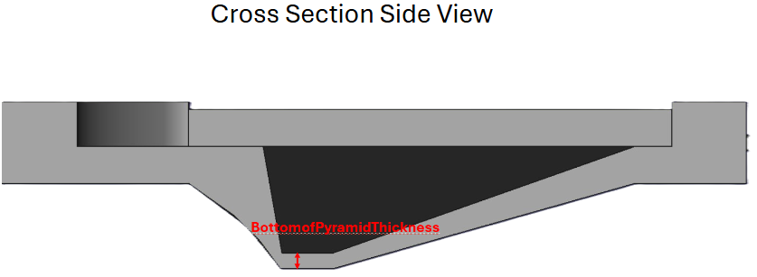 (b) BottomOfPyramidThickness (Section 2.1.6)
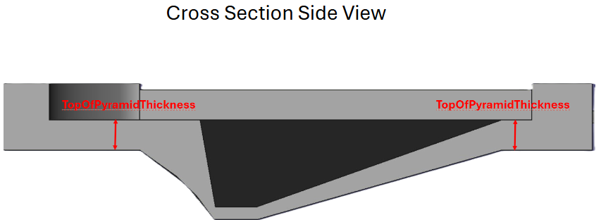
 TopOfPyramidThickness
TopOfPyramidThickness (default: 1mm, 0 < PyramidBackAngle < PyramidDepth) defines the overall thickness of the area around the pyramid section, not including the side walls or the back. This distance starts from the top of the pyramid, and continues down, as shown by the solid red arrows in Figure 3 (a).
This parameter, along with BottomOfPyramidThickness (Section 2.1.6) play a crucial role in the overall structural stability of the pyramid.
BottomOfPyramidThickness
BottomOfPyramidThickness (default: 0.2mm) defines the overall thickness of the hole at the bottom of the pyramid, in which the fly will be mounted (see Figure 3 (b)). This starts from the bottom of the PyramidDepth (Figure 2 (c)) and goes down.
This parameter, along with TopOfPyramidThickness (Section 2.1.5) help define the overall strength of the pyramid and determine the field of view of the fly and view of the microscope.
Fly Hole and Underside Space
 (a) HoleWidth (Section 2.2.1)
 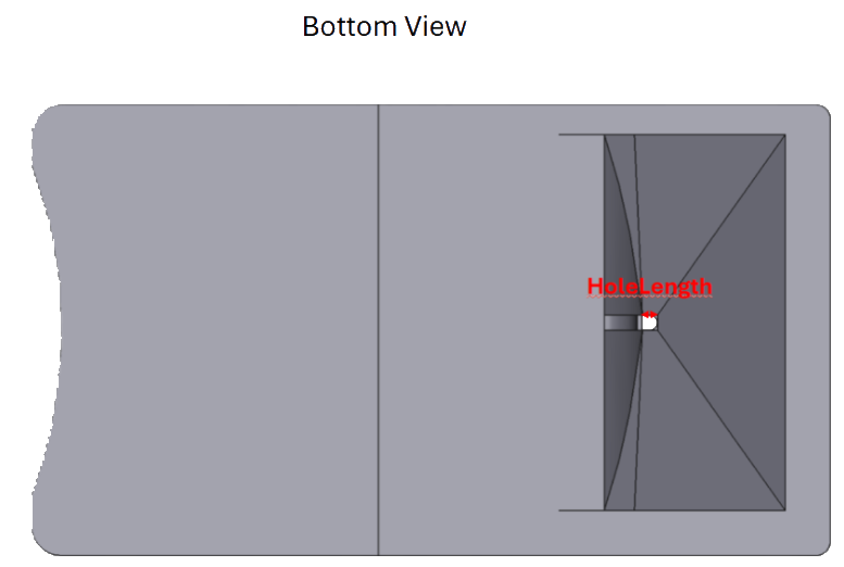 (b) HoleLength (Section 2.2.2)
 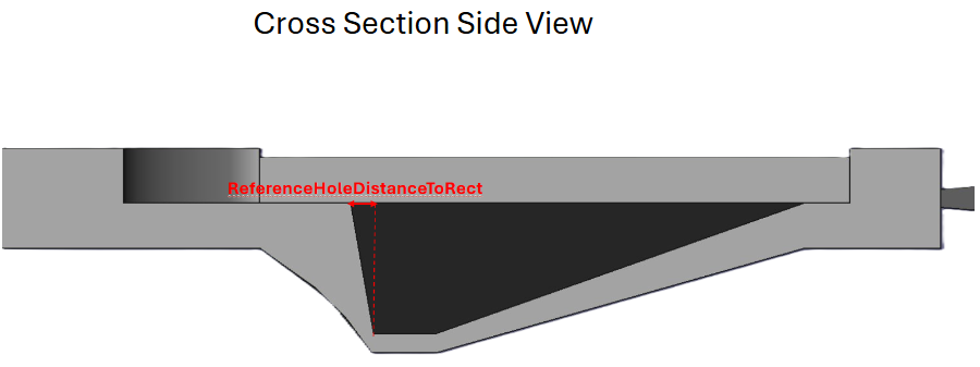 (c) ReferenceHoleDistanceToRect (Section 2.2.3)
 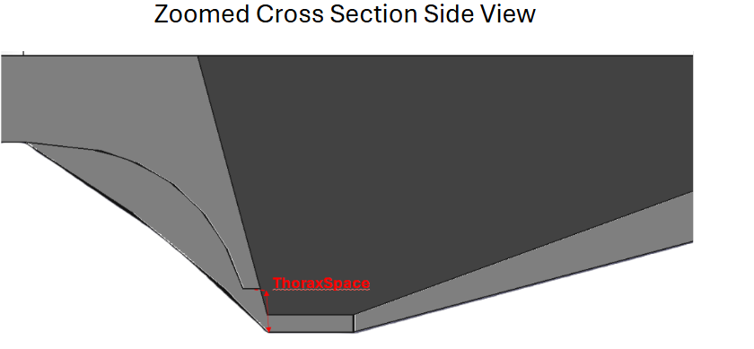 (d) ThoraxSpace (Section 2.2.4)
 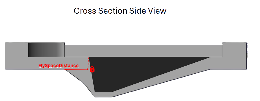 (e) FlySpaceDistance (Section 2.2.5)
 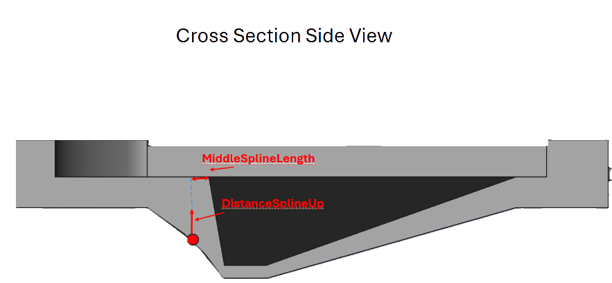 (f) DistanceSplineUp and DistanceSplineLength (Section 2.2.6)
 HoleWidth
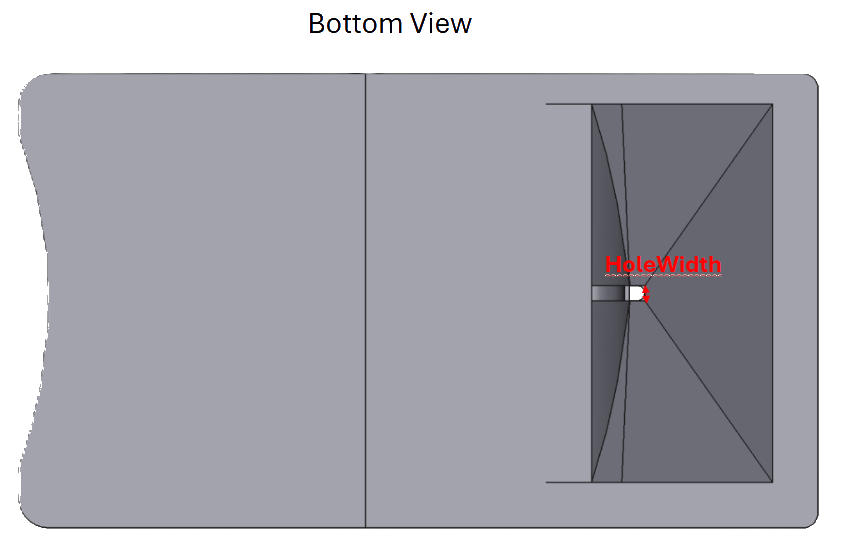
HoleWidth (default: 1mm) defines the total width of the hole in which the fly will be mounted, in the direction of the RectWidth (Section 2.1.2) parameter, as shown by the red arrow in Figure 4 (a).
This parameter, along with HoleLength (Section 2.2.2) helps define the hole in which the fly will be mounted into and is determined on how big the fly is.
HoleLength
HoleLength (default: 1mm) defines the the total length of the hole in which the fly will be mounted (see Figure 4 (b)), in the direction of the RectLength (Figure 2 (a)) parameter.
This parameter, along with HoleWidth (Section 2.2.1) helps define the hole in which the fly will be mounted into and is determined on how big the fly is.
ReferenceHoleDistanceToRect
[!TIP]
Reference
This parameter cannot be changed and is only used as a reference
ReferenceHoleDistanceToRect (default: 0.8mm) defines the overall horizontal distance from the back of hole at the bottom of the pyramid to overall back of the pyramid, as shown by the solid red arrow in Figure 4 (c).
ThoraxSpace
ThoraxSpace (default: 0.5mm, 0 < PyramidBackAngle < (PyramidDepth - TopOfPyramidThickness)) defines the total distance from the bottom of the hole in the pyramid, up the back section of the pyramid, as shown by the solid red arrow in Figure 4 (d).
This cutout helps determine the extra room for the thorax of the fly, which can be altered to more easily mount and position the fly.
FlySpaceDistance
FlySpaceDistance (default: 2mm) determines the total length of the spline underneath the fly starting from the very back of the pyramid, and going backwards, and meeting with the bottom of the model. The side of the arrow, indicated by the lock, does not move when the distance is increased, and the side left of it increases.
This parameter, along with DistanceSplineUp and MiddleSplineLength define the overall shape of the spline in which the fly will be positioned.
DistanceSplineUp / MiddleSplineLength
The bottom space surrounding the fly is defined by a single spline, consisting of three points. DistanceSplineUp and MiddleSplineLength define the middle point position of the spline near the fly. These parameters are lumped together as they both define the same point and cannot be defined independently in a clear way.
DistanceSplineUp (default: 1mm) determines the total depth of the middle point of the spline underneath the model, starting from the bottom of the model, as shown by the solid red arrow in Figure 4 (f).
This parameter, along with FlySpaceDistance and MiddleSplineLength define the overall shape of the spline in which the fly will be positioned.
MiddleSplineLength (default: 0.3mm) determines the total distance of the middle point of the spline underneath the model from the back of the hollowed pyramid section, as shown by the solid red arrow in Figure 4 (f).
This parameter, along with FlySpaceDistance and MiddleSplineLength define the overall shape of the spline in which the fly will be positioned.
Right and Left Edge
This Section only includes the names and descriptions of the right parameters, but the left parameters are the same and are under the Left parameters section in the spreadsheet. The name in brackets denotes the parameter name for the left side.
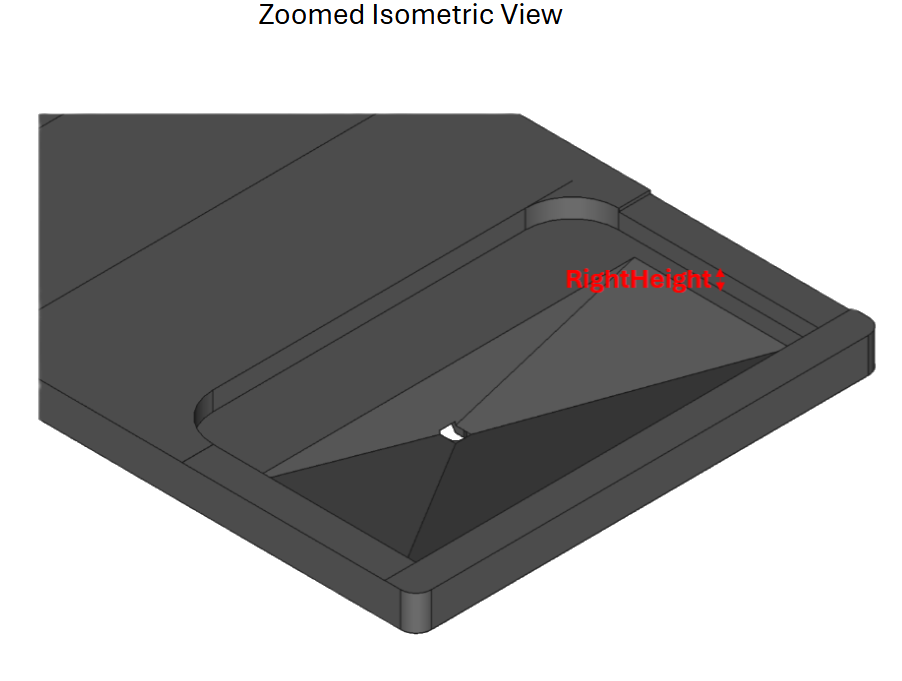 (a) RightHeight (Section 2.3.1)
 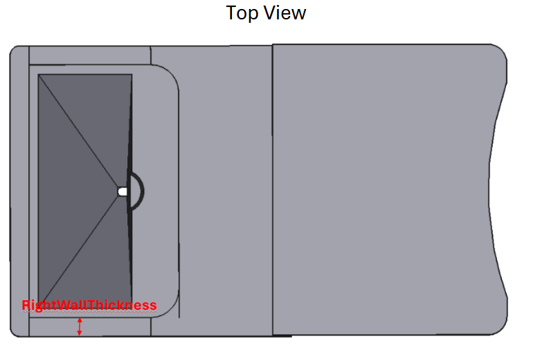 (b) RightWallThickness (Section 2.3.2)
 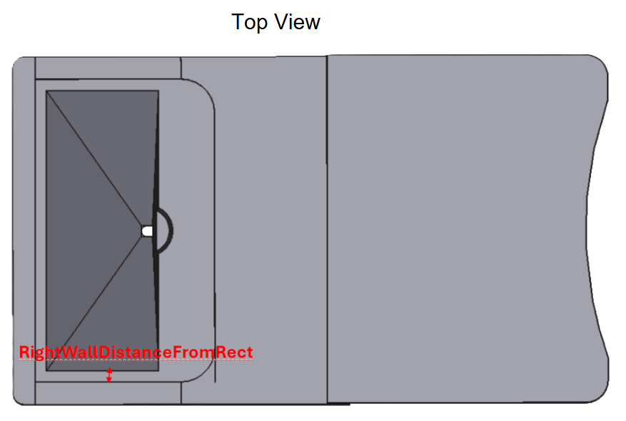 (c) RightWallDistanceFromRect (Section 2.3.3)
 RightHeight (LeftHeight)
RightHeight (LeftHeight, default: 1.2mm) determines the height of the right edge of the pyramid, starting from the top of the pyramid section (see Figure 5 (a)).
The parameters of the two sides together determine the overall height of the two edges. Height cannot go above the UpperDepth parameter, which is the height of the surrounding features around it. Furthermore, this height does not include the height of the area surrounding the pyramid, so setting it to 0 reverts to the area surrounding the pyramid’s height. If this height needs to be set to the surrounding edges, setting it high will do so.
RightWallThickness (LeftWallThickness)
RightWallThickness (LeftWallThickness, default: 2mm) determines the overall thickness of the right wall, starting from the RightWallDistanceFromRect (LeftWallDistanceFromRect) parameter (see Figure 5 (b)).
This parameter, along with RightWallDistanceFromRect (LeftWallDistanceFromRect) defines the extra distance of the model from the sides of the pyramid and increases the overall stability of the design.
RightWallDistanceFromRect (LeftWallDistanceFromRect)
RightWallDistanceFromRect (LeftWallDistanceFromRect, default: 2mm) defines the total distance from the edge of the top of the pyramid, to the start of the right wall (see Figure 5 (c)).
This parameter, along with RightWallThickness (LeftWallThickness) defines the extra distance of the model from the sides of the pyramid and increases the overall stability of the design.
Upper Section
 (a) UpperBackDistanceToRect (Section 2.4.1)
 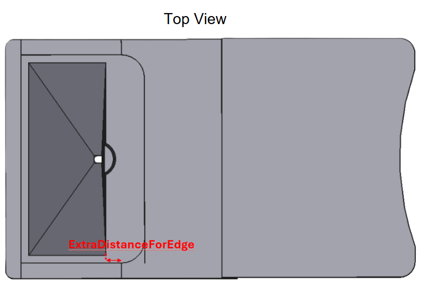 (b) ExtraDistanceForEdge (Section 2.4.2)
 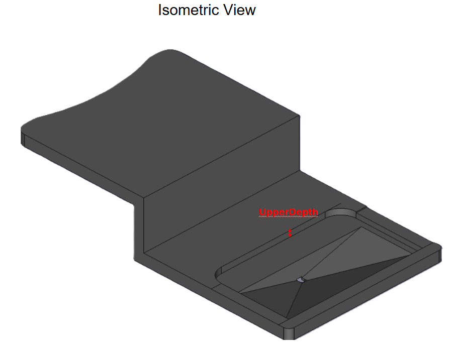 (c) UpperDepth (Section 2.4.3)
 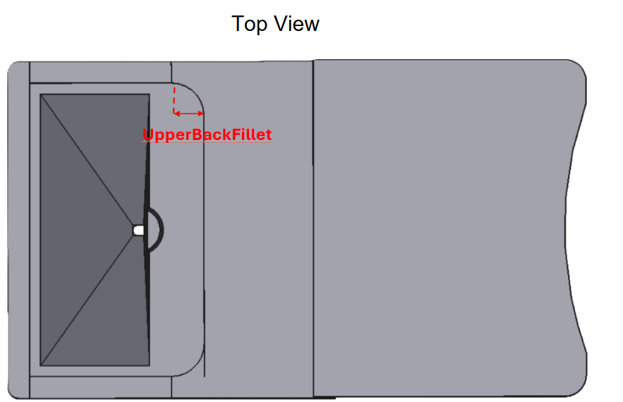 (d) UpperBackFillet (Section 2.4.4)
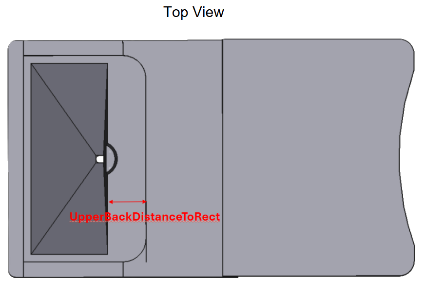
 UpperBackDistanceToRect
UpperBackDistanceToRect (default: 5mm) defines the total distance from the back of the pyramid to the start of the higher section in the back (see Figure 6 (a)).
This parameter, along with UpperBackFillet (see Section 2.4.4) help define the extra space behind the back pyramid and is helpful for allowing possible fluids into the pyramid section or extra space for a microscope lens.
ExtraDistanceForEdge
ExtraDistanceForEdge (default: 2mm, 0 < ExtraDistanceForEdge < UpperBackDistanceToRect) defines the start of the right and left sections of the edge, starting from the back of the pyramid (see Figure 6 (b)).
This parameter, along with the RightHeight (LeftHeight) parameter (Section 2.3.1), provides potential extra space for entering from the side of the pyramid.
UpperDepth
UpperDepth (default: 1.2mm) defines the overall depth of the back of the plate, starting from the top of the pyramid section (see Figure 6 (c)). This parameter also sets the thickness of the front portion of the model.
This parameter, along with TopOfPyramidThickness (Section 2.1.5) set the overall thickness of the back plate and the front section of the model.
UpperBackFillet
UpperBackFillet (default: 3mm) defines the radius of the fillet behind the back of the pyramid and before the higher section of the back plate (see Figure 6 (d)).
This paramter, along with UpperBackDistanceToRect (Section 2.4.1) and ExtraDistanceForEdge (Section 2.4.2) define the shape of the fillet in the behind the pyramid section and will automatically be set lower if it is too high.
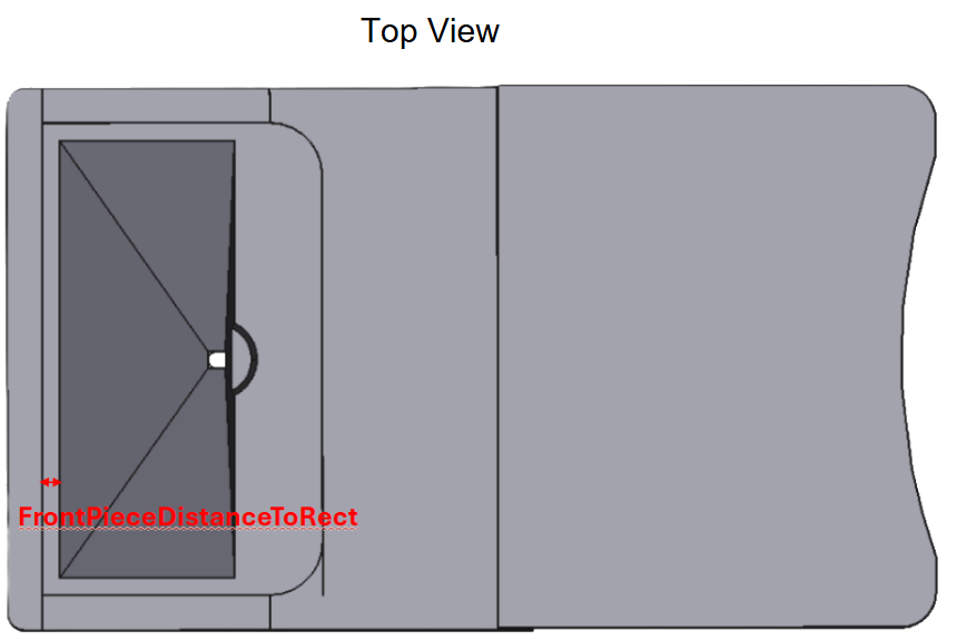 (a) FrontPieceDistanceToRect (Section 2.4.5)
 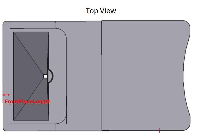 (b) FrontPieceLength (Section 2.4.6)
 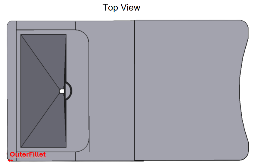 (c) OuterFillet (Section 2.4.7)
 FrontPieceDistanceToRect
FrontPieceDistanceToRect (default: 0mm) defines the overall distance from the front of the pyramid to the start of the higher, front edge of the model (see Figure 7 (a)).
This parameter along with FrontPieceLength (Section 2.4.6) and OuterFillet (Section 2.4.7) define the overall shape of the front of the model.
FrontPieceLength
FrontPieceLength (default: 2mm) defines the overall thickness of the front edge of the model (see Figure 7 (b)).
This parameter along with FrontPieceDistanceToRect (Section 2.4.5) and OuterFillet (Section 2.4.7) define the overall shape of the front of the model.
OuterFillet
OuterFillet (default: 1mm) defines the overall radius of both fillets on the front end of the model, as shown by the solid red arrow at the bottom left in Figure 7 (c).
This parameter along with FrontPieceLength (Section 2.4.6) and FrontPieceDistanceToRect (Section 2.4.5) define the overall shape of the front of the model and will be automatically set to its max if set too high.
Back Plate
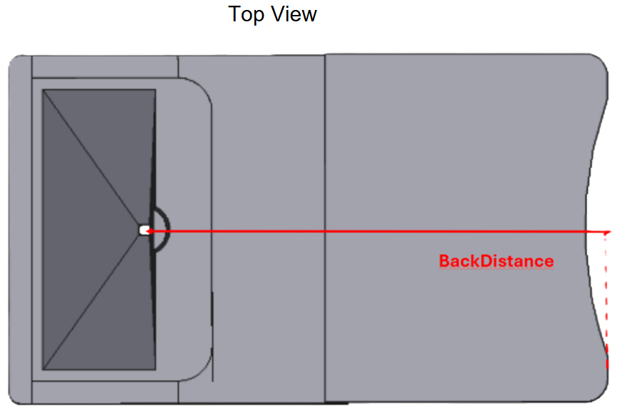 (a) BackDistance (Section 2.5.1)
 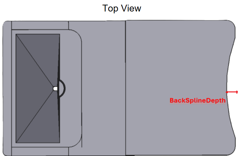 (b) BackSplineDepth (Section 2.5.2)
 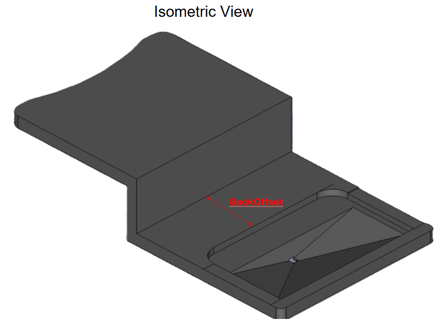 (c) BackOffset (Section 2.5.3)
 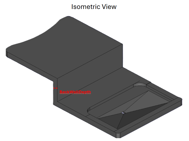 (d) BackWallDepth (Section 2.5.4)
 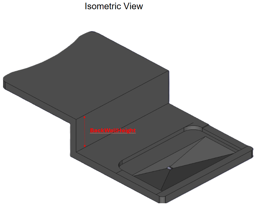 (e) BackWallHeight (Section 2.5.5)
 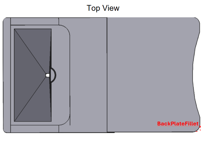 (f) BackPlateFillet (Section 2.5.6)
 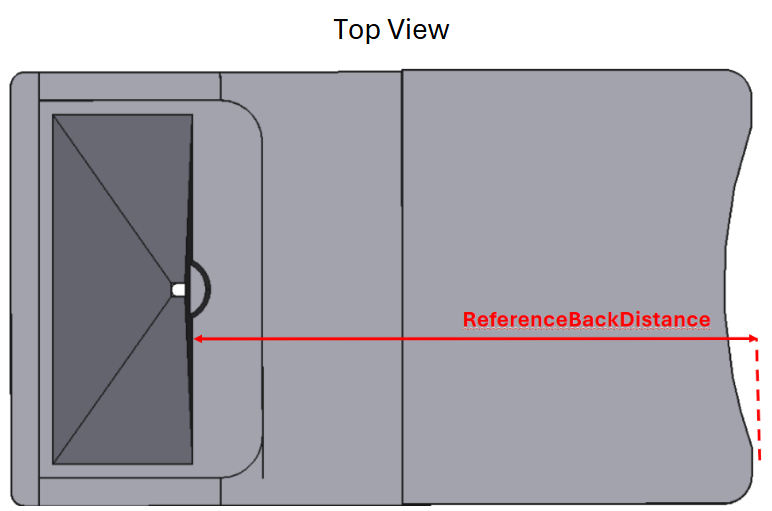 (g) ReferenceBackDistance (Section 2.5.7)
 BackDistance
BackDistance (default: 40mm) defines the overall distance from the middle of the hole in the pyramid to the very back of the model (see Figure 8 (a)).
This parameter, along with BackOffset (Section 2.5.3) and BackWallHeight (Section 2.5.5) help define the overall sections of the back plate model horizontally. If this parameter is set too low (less than the BackOffset + UpperDistanceToRect + BackSplineDepth), it will automatically be set to its minimum it can work with.
BackSplineDepth
BackSplineDepth (default: 4mm) defines the overall depth of the spline in the back of the model, starting from the very back of the model (see Figure 8 (b)). This dimension can never be less than TopOfPyramidThickness, and will be auto set to the TopOfPyramidThickness (Section 2.1.5) if it is less than it.
This parameter, along with BackPlateFillet (Section 2.5.6) help define the overall shape of the back of the model and can provide easier mounting for the model.
BackOffset
BackOffset (default: 10mm) defines the overall distance starting from the upper portion of the back of the model to the back wall of the model (see Figure 8 (c)).
This parameter, along with BackDistance (Section 2.5.1) helps to define the overall sections of the back plate of the model.
BackWallDepth
BackWallDepth (default: 2mm) defines the overall thickness of the back wall of the model (see Figure 8 (d)).
This parameter, along with BackWallHeight (Section 2.5.5) help to define the overall shape of the back wall of the model, which can be used to get better images from the back of the model.
BackWallHeight
BackWallHeight (default: 10mm) defines the overall height of the back wall of the model, starting from the top of the back of the upper section behind the pyramid, to the top of the higher back plate (see Figure 8 (e)).
This parameter, along with BackWallDepth (Section 2.5.5) help define the overall shape of the back wall and can be used to get better images from the back of the model. This parameter can also be set to 0 to make the model flat.
BackPlateFillet
BackPlateFillet (default: 1mm) defines the total radius of the fillet on each side of the back plate of the model (see Figure 8 (f)).
This parameter, along with BackSplineDepth (Section 2.5.2) helps to define the overall shape of the very back of the model and can be used for easier mounting or clamping for the model.
ReferenceBackDistance
[!TIP]
Reference
This parameter cannot be changed and is only used as a reference
ReferenceBackDistance (default: 38.6mm) is a reference parameter that shows the overall distance from the back of the pyramid section to the very back of the model, as shown by the solid red arrow in Figure 8 (g).
Microscope Lens
This cutout can be removed by increasing the working distance to higher than the depth of the pyramid.
 (a) ObjectiveDiameter (Section 2.6.1)
 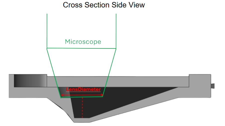 (b) LensDiameter (Section 2.6.2)
 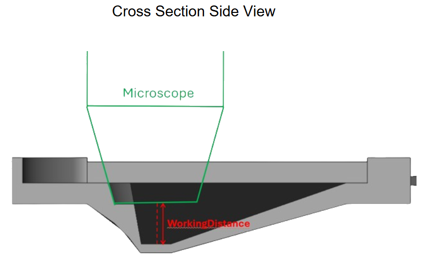 (c) WorkingDistance (Section 2.6.3)
 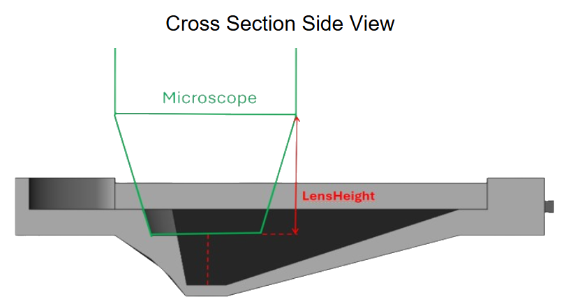 (d) LensHeight (Section 2.6.4)
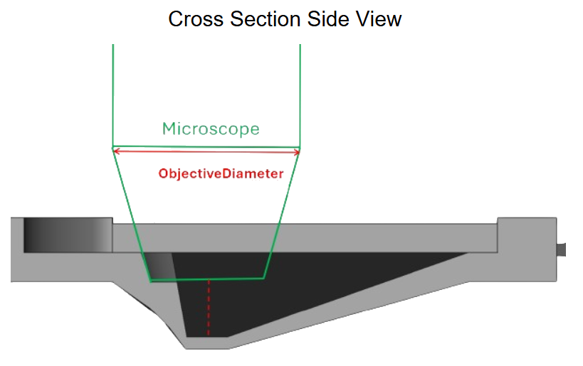
 ObjectiveDiameter
ObjectiveDiameter (default: 10mm) defines the overall diameter of the objective of the microscope cutout, as shown by the solid red arrow in Figure 9 (a), which is centered at the middle of the fly pyramid hole.
This parameter, along with LensHeight (Section 2.6.4), WorkingDistance (Section 2.6.3), and LensDiameter (Section 2.6.2) defines the overall shape of the microscope cutout, which can be used to judge how well the microscope meshes with the design and to provide more space for the microscope.
LensDiameter
LensDiameter (default: 4mm) defines the overall diameter of the lens of the microscope cutout, as shown by the solid red arrow in Figure 9 (b), which is centered at the middle of the fly pyramid hole.
This parameter, along with LensHeight (Section 2.6.4), WorkingDistance (Section 2.6.3), and ObjectiveDiameter (Section 2.6.1) defines the overall shape of the microscope cutout, which can be used to judge how well the microscope meshes with the design and to provide more space for the microscope.
WorkingDistance
WorkingDistance (default: 2mm) defines the overall distance from the top of the hole at the bottom of the pyramid to the bottom of the lens, as shown by the solid red arrow in Figure 9 (c).
This parameter, along with LensHeight (Section 2.6.4), LensDiameter (Section 2.6.2), and ObjectiveDiameter (Section 2.6.1) defines the overall shape of the microscope cutout, which can be used to judge how well the microscope meshes with the design and to provide more space for the microscope.
LensHeight
LensHeight (default: 2mm) defines the overall distance from the objective to the lens, as shown by the solid red arrow in Figure 9 (d).
This parameter, along with WorkingDistance (Section 2.6.3), LensDiameter (Section 2.6.2), and ObjectiveDiameter (Section 2.6.1) defines the overall shape of the microscope cutout, which can be used to judge how well the microscope meshes with the design and to provide more space for the microscope.
Bottom Supports
 Figure 10: Bottom Supports
 ConeTopDiameter
ConeTopDiameter (default: 0.7mm) defines the overall diameter of each cone supporting the bottom of the pyramid, as shown by the red arrow near the bottom right in Figure 10.
This parameter, along with ConeTaper (Section 2.7.2) define the overall shape of each cone supporting the model.
ConeTaper
ConeTaper (default: 10°) defines the overall taper angle of each cone supporting the model, as shown by the triangle near the bottom left of the model in Figure 10.
This parameter, along with ConeTopDiameter (Section 2.7.1) defines the overall shape of each supporting model.
BottomExtraDistance
BottomExtraDistance (default: 0.5mm) defines the overall extra distance of each side of the back plate from the model, as shown by the red arrow on the bottom right in Figure 10.
This parameter defines the extra distance of the plate to support the model and allows for the model to be properly supported from underneath.
BottomChamfer
BottomChamfer (default: 0.5mm, 0 <= BottomChamfer < SupportPlateDepth) defines the total chamfer on the front and back ends of the support plate, as shown by the solid red arrow in the bottom right in Figure 10.
This parameter allows for the support plate to be taken off more easily from the build plate.
DistanceBetweenCones
DistanceBetweenCones (default: 1.75mm) defines the distance between the edges of each cone to each other connected to the bottom of the pyramid model, as shown by the solid red arrow near the middle of Figure 10.
This parameter, along with ConeTopDiameter (Section 2.7.1) defines how many cones are supporting the model and how well it is supported.
ConeDistance
ConeDistance (default: 3mm) defines the overall height of each cone, starting from the bottom of the model to the top of the support plate, as shown by the red arrow in the bottom middle of Figure 10.
This parameter, along with ConeTopDiameter (Section 2.7.1) and ConeTaper (Section 2.7.2) define the overall shape of each cone.
SupportPlateDepth
SupportPlateDepth (default: 2mm) defines the total depth of the support plate, as shown by the red arrow in the bottom left of Figure 10.
This parameter, along with BottomExtraDistance (Section 2.7.3) and BottomChamfer (Section 2.7.4) defines the overall shape of the support plate — and can be used to increase the strength of the support plate.
Side Supports
 (a) Side Suppors as seen from the top
  (b) Side Suppors as seen from the side
 SupportLength
Default value: 0.6 mm
SupportLength (default: 0.6mm) defines the overall vertical distance of each support connected to the front of the pyramid model, as shown by the red arrow in the middle of Figure 11 (a).
This parameter, along with SupportThickness (Section 2.8.2) define the shape of each individual support connected to the fly pyramid side.
SupportThickness
SupportThickness (default: 0.4mm) defines the overall horizontal distance of each support connected to the front of the pyramid model, as shown by the red arrow in the middle of Figure 11 (b).
This parameter, along with SupportLength (Section 2.8.1) define the shape of each individual support connected to the fly pyramid side.
ConnectionLength
ConnectionLength (default: 3.5mm) defines the overall distance of each support from the side of the pyramid model to the start of the side-support plate, as shown by the red arrow near the top of Figure 11 (a).
This parameter, along with SupportLength (Section 2.8.1) and SupportThickness (Section 2.8.2) helps define the overall ease of removing the side supports from the model.
SupportDistanceFromBottom
SupportDistanceFromBottom (default: 2mm) defines the overall distance from the bottom of the first support to the bottom of the entire model. This parameter also defines the overall length of each support on the side of the support plate, as shown by the red arrow in Figure 11 (a).
This parameter, along with ConnectorWidth (Section 2.8.5) defines the overall dimensions of each support connected to the support plate side.
ConnectorWidth
ConnectorWidth (default: 1mm) defines the overall width of each support on the support plate side, as shown by the red arrow in Figure 11 (b).
This parameter, along with the SupportDistanceFromBottom parameter (Section 2.8.4) defines the overall dimensions of each support connected to the support plate side.
ExtraPlateDistance
ExtraPlateDistance (default: 2mm) defines the extra length on each side of the supports of the support plate, as shown by the red arrow in Figure 11 (b).
This parameter, along with SidePlateThickness (Section 2.8.8) determines the overall shape of the side support plate.
NumberOfSideSuppports
NumberOfSideSupports (default: 8) defines the total number of sides supports supporting the model.
This parameter helps define how well the entire side of the model is supported.
SidePlateThickness
SidePlateThickness (default: 3mm) determines the overall thickness of the side support plate, as shown in the Figure 11 (a).
Fly Field of View Reference Angles
These parameters are shown as reference in the FreeCAD spreadsheet and display the possible field of view that the fly would have if mounted in that particular setup.
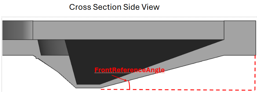 (a) FrontReferenceAngle (Section 2.9.1)
 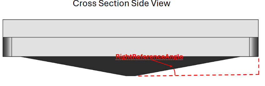 (b) RightReferenceAngle (Section 2.9.2)
 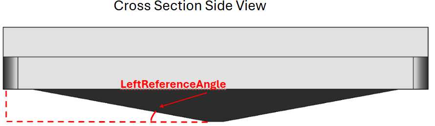 (c) LeftReferenceAngle (Section 2.9.3)
 FrontReferenceAngle
[!TIP]
Reference
This parameter cannot be changed and is only used as a reference
FrontReferenceAngle (default: 12°) measures the angle from the very bottom-front of the fly hole, where the fly eyes will likely be close to, all the way to the very end of the model, as shown by the red angle in Figure 12 (a).
This parameter, along with LeftReferenceAngle (Section 2.9.3) and RightReferenceAngle (Section 2.9.2) show the field of view that the fly can see with a specific pyramid model.
RightReferenceAngle
[!TIP]
Reference
This parameter cannot be changed and is only used as a reference
RightReferenceAngle (default: 9°) measures the angle from the very bottom-right of the fly hole, where the fly eyes will likely be close to, all the way to the very right end of the model, as shown by the red angle in Figure 12 (b).
This parameter, along with LeftReferenceAngle (Section 2.9.3) and FrontReferenceAngle (Section 2.9.1) show the field of view that the fly can see with a specific pyramid model.
LeftReferenceAngle
[!TIP]
Reference
This parameter cannot be changed and is only used as a reference
LeftReferenceAngle (default: 9°) measures the angle from the very bottom-left of the fly hole, where the fly eyes will likely be close to, all the way to the very left end of the model, as shown by the red angle in Figure 12 (c).
This parameter, along with FrontReferenceAngle (Section 2.9.1) and RightReferenceAngle (Section 2.9.2) show the field of view that the fly can see with a specific pyramid model.
Print Instructions
FreeCAD export instructions
 (a) Switch to the *Mesh* workspace in FreeCAD
  (b) Convert parametrizable FreeCAD bodies to static meshes
  (c) Merge several meshes into a single exportable object
 This can be skipped if FreeCAD is not being used to parameterize the model, and the default 3D files are being used.
After editing the parameters of the FreeCAD model, exit out to the main menu. Next, click on the dropdown on the top bar of the screen that says Part Design or Start under the Windows button, and change the dropdown menu to Mesh (see Figure 13 (a)).
After this, select the Fly Pyramid Body, Bottom Supports, and SideSupports folders on the left, as seen below, and click on the Create Mesh From Shape option, and select the Ok button with the default settings (see Figure 13 (b)). This will generate meshes of the selected bodies with the same base name and the addition (Meshed).
After this, select all the new meshes and click the merge button, on the top toolbar (see Figure 13 (c)). This generates a single mesh for all the different bodies.
With this final mesh, turn off the visibility of all the other objects to make sure that there are no glitches or holes in the design, and then right click on the final singular mesh and select Export Mesh… as a *.stl file. After this, the mesh objects can be deleted.
Slicer Setup Tutorial
The slicer software being used is called Lychee Slicer.
After setting up the settings of the printer in the software and importing the fly pyramid (stl or obj file) model into the slicer. The fly pyramids should be printed individually and not connected to each other, with the bottom supports laying on the plate. However, it is recommended that the fly pyramids are printed relatively close to each other, to minimize possible damage from the sloshing of the liquid resin (this is not determined to be a big problem, but it is best to be safe). After this, export the model and print it.
 Figure 14: Example of pyramids in the Lychee slicer
 Build Plate Removal
After the prints are finished being printed, carefully remove the build plate from the printer, and lay it flat on the table. After this, use a small razor blade to scrape under the bottom supports near the back of the model, until the bottom supports are loose. Next, use the razor, or even your finger, to apply pressure to the bottom of the side supports, until they come loose. All of this is shown in the following short video.
/Fly-Lab-Gear/assets/img/Physiology-Setup/Parametric-Flypyramid/Fly_Pyramid_Removal.mov
After this, you can wash each of the prints, with either IPA or water (depending on the resin being used), and then cure it for around 5-10 minutes to solidify the resin.
Recommended Resins and Exposure Times
Throughout designing and testing the newly designed fly-pyramids, 5 different resins were tested with various thicknesses and measurements. The strength of each resin was determined by the total downward force that the bottom of the hole could support before reaching failure. This was measured by placing a small wire through the hole, with a stopper at the top, which prevents the wire from passing all the way through the hole. After this, weight is applied downward on the wire with a small bucket and weights inside. This setup is shown in Figure 15.
A variety of fly pyramids with different resins, BottomOfPyramidThickness (Figure 3 (b)) and TopOfPyramidThickness (Figure 3 (a)) measurements were measured. Each resin was tested with three BottomOfPyramidThickness measurements (0.1mm, 0.15mm, 0.2mm) and two TopOfPyramidThickness measurements (0.5mm and 1mm). Each of these combination’s max weight held (g) was measured twice, accounting for 12 tests per resin, as seen in the Table 1.
The full data sheet can be seen here: Strength Test Results.xlsx The following graph displays the total strength measurements for each of the five resins. The X-axis represents the ”BottomPyramidThickness” and the Y-axis measures the maximum weight held per pyramid. Each color in the graph represents the measurements for a particular resin, as shown by the legend. Furthermore, x represent measurements with a TopOfPyramidThickness of 0.5mm (see Figure 3 (a)) and + represent ones with a thickness of 1mm.
Each resin was printed with the following exposure times on the Elegoo Mars 3 printer:
However, some rough tests have shown that potentially decreasing the layer height (down to 0.025 mm) can increase the quality and strength of the print, with the cost of increased printing time.
Appendix
Strength test
Measurements from the strenght test of different resins. All the data is visualized in Figure 16
Table 1: Measured maximum weight per resin at different print settings
| Resin Type | BottomOfPyramidThickness | TopOfPyramidThickness | weight |
|---|---|---|---|
| Phrozen TR250 | 0.1 | 0.5 | 200 |
| Phrozen TR250 | 0.1 | 0.5 | 195 |
| Phrozen TR250 | 0.15 | 0.5 | 414 |
| Phrozen TR250 | 0.15 | 0.5 | 465 |
| Phrozen TR250 | 0.2 | 0.5 | 733 |
| Phrozen TR250 | 0.2 | 0.5 | 764 |
| Phrozen TR250 | 0.1 | 1 | 255 |
| Phrozen TR250 | 0.1 | 1 | 276 |
| Phrozen TR250 | 0.15 | 1 | 548 |
| Phrozen TR250 | 0.15 | 1 | 546 |
| Phrozen TR250 | 0.2 | 1 | 966 |
| Phrozen TR250 | 0.2 | 1 | 995 |
| Elegoo Standard | 0.1 | 0.5 | 90 |
| Elegoo Standard | 0.1 | 0.5 | 96 |
| Elegoo Standard | 0.15 | 0.5 | 147 |
| Elegoo Standard | 0.15 | 0.5 | 185 |
| Elegoo Standard | 0.2 | 0.5 | 430 |
| Elegoo Standard | 0.2 | 0.5 | 431 |
| Elegoo Standard | 0.1 | 1 | 160 |
| Elegoo Standard | 0.1 | 1 | 120 |
| Elegoo Standard | 0.15 | 1 | 318 |
| Elegoo Standard | 0.15 | 1 | 300 |
| Elegoo Standard | 0.2 | 1 | 431 |
| Elegoo Standard | 0.2 | 1 | 475 |
| Elegoo ABS-like 3.0 | 0.1 | 0.5 | 66 |
| Elegoo ABS-like 3.0 | 0.1 | 0.5 | 101 |
| Elegoo ABS-like 3.0 | 0.15 | 0.5 | 297 |
| Elegoo ABS-like 3.0 | 0.15 | 0.5 | 302 |
| Elegoo ABS-like 3.0 | 0.2 | 0.5 | 490 |
| Elegoo ABS-like 3.0 | 0.2 | 0.5 | 520 |
| Elegoo ABS-like 3.0 | 0.1 | 1 | 120 |
| Elegoo ABS-like 3.0 | 0.1 | 1 | 120 |
| Elegoo ABS-like 3.0 | 0.15 | 1 | 300 |
| Elegoo ABS-like 3.0 | 0.15 | 1 | 356 |
| Elegoo ABS-like 3.0 | 0.2 | 1 | 718 |
| Elegoo ABS-like 3.0 | 0.2 | 1 | 710 |
| Anycubic ABS-like Pro 2 | 0.1 | 0.5 | 66 |
| Anycubic ABS-like Pro 2 | 0.1 | 0.5 | 66 |
| Anycubic ABS-like Pro 2 | 0.15 | 0.5 | 88 |
| Anycubic ABS-like Pro 2 | 0.15 | 0.5 | nan |
| Anycubic ABS-like Pro 2 | 0.2 | 0.5 | 96 |
| Anycubic ABS-like Pro 2 | 0.2 | 0.5 | 82 |
| Anycubic ABS-like Pro 2 | 0.1 | 1 | 103 |
| Anycubic ABS-like Pro 2 | 0.1 | 1 | nan |
| Anycubic ABS-like Pro 2 | 0.15 | 1 | 152 |
| Anycubic ABS-like Pro 2 | 0.15 | 1 | 162 |
| Anycubic ABS-like Pro 2 | 0.2 | 1 | 195 |
| Anycubic ABS-like Pro 2 | 0.2 | 1 | 232 |
| Anycubic Rigid 100 | 0.1 | 0.5 | 341 |
| Anycubic Rigid 100 | 0.1 | 0.5 | 317 |
| Anycubic Rigid 100 | 0.15 | 0.5 | 586 |
| Anycubic Rigid 100 | 0.15 | 0.5 | 613 |
| Anycubic Rigid 100 | 0.2 | 0.5 | 976 |
| Anycubic Rigid 100 | 0.2 | 0.5 | 985 |
| Anycubic Rigid 100 | 0.1 | 1 | 394 |
| Anycubic Rigid 100 | 0.1 | 1 | 371 |
| Anycubic Rigid 100 | 0.15 | 1 | 655 |
| Anycubic Rigid 100 | 0.15 | 1 | 678 |
| Anycubic Rigid 100 | 0.2 | 1 | 1112 |
| Anycubic Rigid 100 | 0.2 | 1 | 1096 |
Document History
- originally a Word document by Benjamin Hayworth (Summer intern from Loudoun County High Schools )
- converted to private GitHub compatible Markdown
- converted to quarto Markdown for MCN-NET documentation