Fly Spoon: A reference of the parametrically designed fly holder
Introduction
The fly spoon is an accessory model used in imaging experiments with Drosophila melanogaster. This version of the fly holder is meant to be printed with a resin printer with the provided model supports. This edition of the fly spoon is optimized for customizability and parameterization for resin 3d printing. Drosophila, microscopes, and mounting equipment vary in size and shape, and will often cause necessary changes in the fly holder design. This model allows for a wide range of customization in design and accessibility.
The current model of the Fly Spoon was designed in a free, open source 3d modeling software called FreeCAD, which is available for all major platforms (Linux, Windows, and Mac). FreeCAD can be downloaded here: https://www.freecad.org/downloads.php This design was created in FreeCAD version 0.21.2, and made in the weekly version of FreeCAD, found here: Release weekly-builds · FreeCAD/FreeCAD-Bundle · GitHub To properly parameterize the model, any latest weekly version after version “38314” will work. However, due to unknown complications the parameterization of this model so far only works on Windows (Linux does not work with it).
A tutorial to print the model and the best settings are shown at the end of the document. The FreeCAD file(.FCstd), which can be used to parameterize the model, cannot be directly printed. Instead, the FreeCAD model needs to be exported either as an OBJ or as an STL, which will be shown at the end of the document. Furthermore, the default OBJ and STL files, which cannot be parameterized and include only default settings, are also linked in the GitHub below. Both the OBJ and STL files, however, can be directly imported into a slicer to be 3d-printed. In general, stl files were used. However, in rare cases, the preferable STL format led to erroneous rendering in the Lychee slicer software. Switching to the OBJ file format solved this problem. In GitHub, both formats are provided to work around similar issues.
GitHub Link: Component-Designs/Physiology-Setup/Flyplate at main · reiserlab/Component-Designs · GitHub
Overview
The following documentation describes the parameters and customization of the Fly Spoon Model for application in various experiments. To change the following parameters, open the FreeCAD file and click on Fly Spoon Parameters near the top left. This will open a spreadsheet with a list of parameters and values as shown below. Values on a yellow background can be modified, red parameters are “read only” references that are calculated by the model and based on the modified parameters.
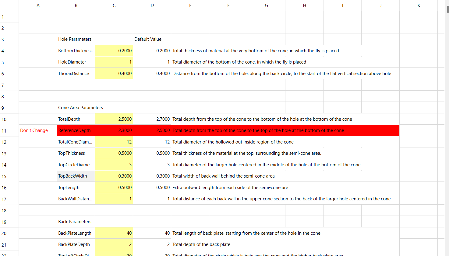
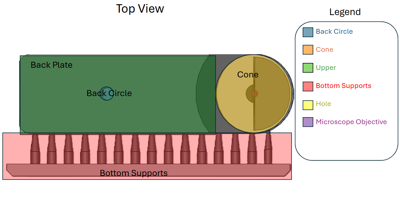
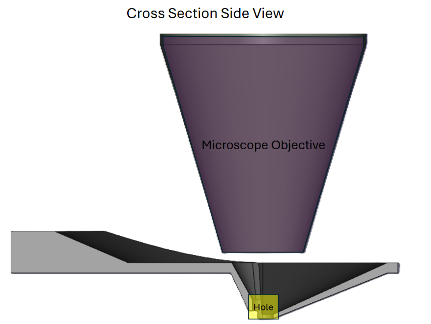
Figure 1: Example list of parameters for the Fly spoon and different views on the CAD model within FreeCAD.
The Fly Spoon Design and its parameters will be grouped into the following sections to make the documentation and labeling easier to follow. The image below displays the sections and names of each.
Hole
 (a) BottomThickness (Section 2.1.1)
 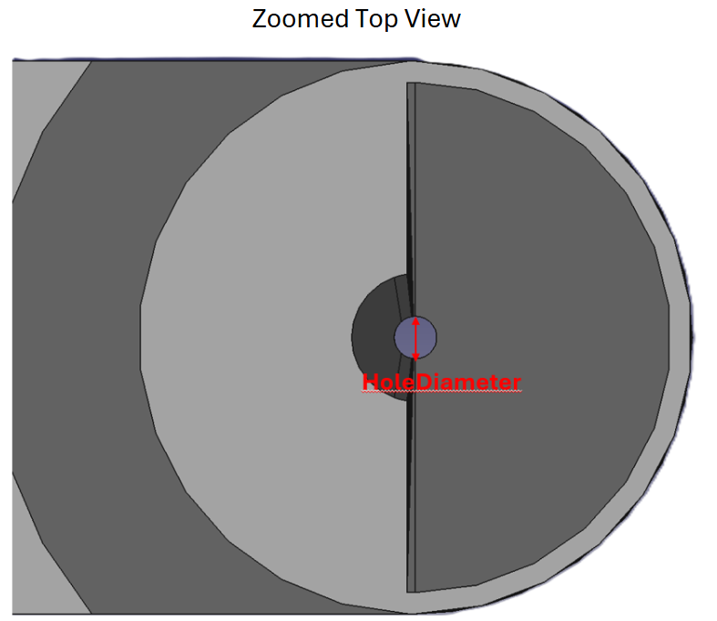 (b) HoleDiameter (Section 2.1.2)
 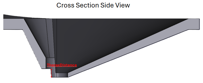 (c) ThoraxDistance (Section 2.1.3)
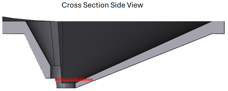
 BottomThickness
BottomThickness (default: 0.2mm) describes the total thickness of the material at the bottom of the cone. This is also where the fly is mounted.
This parameter, along with the TopThickness (Figure 3 (c)) parameter helps define the overall thickness of the material at the bottom and top of the cone area, which can greatly affect the strength of the model and the field of view of the mounted fly.
HoleDiameter
HoleDiameter (default: 1mm) defines the total diameter of the hole at the bottom of the cone, as shown by the red arrow. This is also where the fly will be mounted.
This parameter, along with the ThoraxDistance (Figure 2 (c)) parameter determines the space to mount a fly.
ThoraxDistance
ThoraxDistance (default: 0.4mm) determines the overall vertical distance from the very bottom of the hole, as shown by the red arrow. This is also where the thorax of the fly will be placed.
This parameter, along with the *HoleDiameter (Figure 2 (b)) parameter determines how much space the area where the fly is mounted will have.
Cone Area
 (a) TotalDepth (Section 2.2.1)
 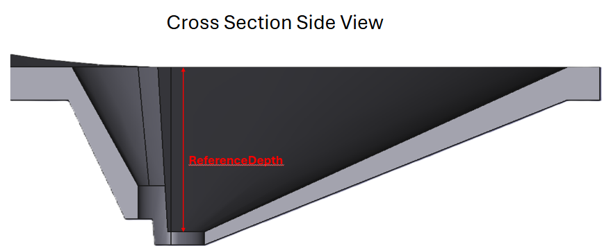 (b) ReferenceDepth (Section 2.2.2)
 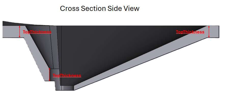 (c) TopThickness (Section 2.2.4)
 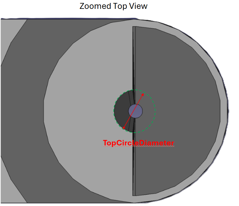 (d) TopCircleDiameter (Section 2.2.5)
 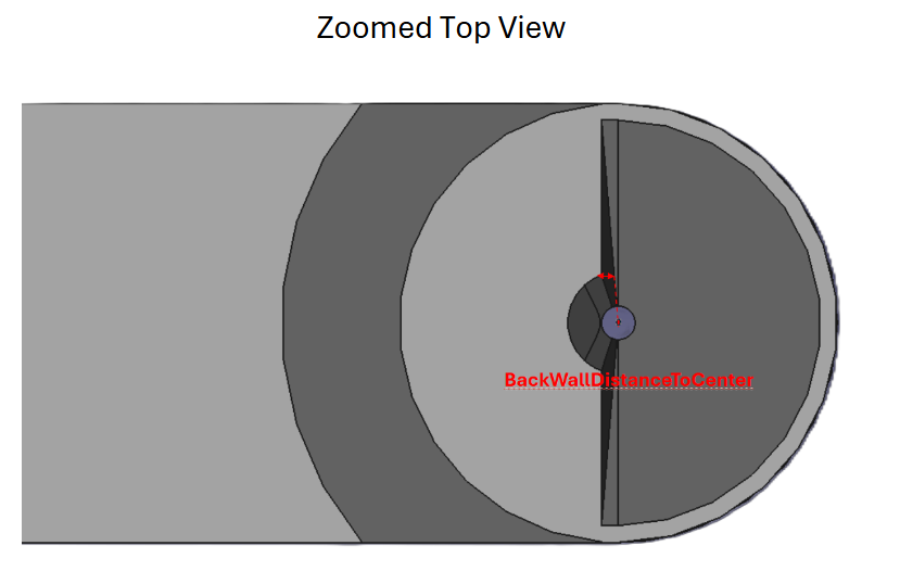 (e) BackWallDistanceToCenter (Section 2.2.6)
 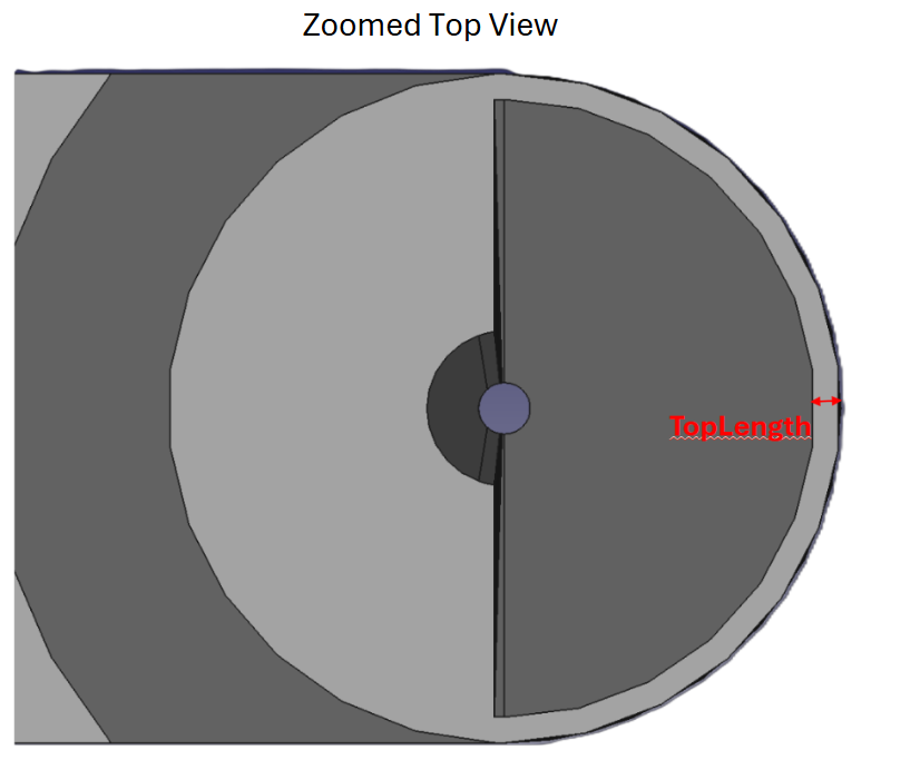 (f) TopLength (Section 2.2.7)
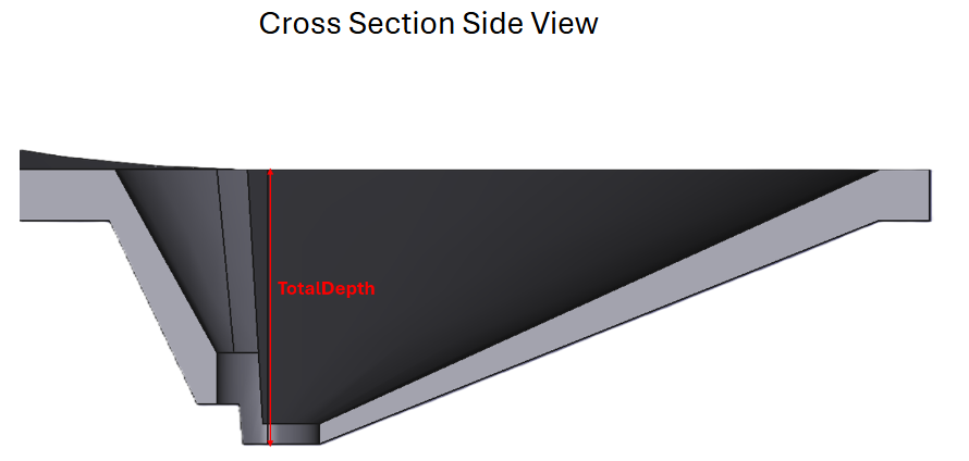
 TotalDepth
TotalDepth (default: 2.5mm) determines the overall depth from the top of the cone area to the bottom of the hole at the bottom of the cone, as shown by the red arrow.
This parameter includes the depth of the hole (“BottomThickness”, Figure 2 (a)) and measures the entire depth of the model.
ReferenceDepth
[!TIP]
Reference
This parameter is only used as reference and cannot be changed
ReferenceDepth (default: 2.5mm) determines the overall depth from the top of the cone area to the top of the hole at the bottom of the cone, as shown by the red arrow.
This parameter does not include the depth of the hole (“BottomThickness”, Figure 2 (a)), and only considers the distance without the hole thickness.
TotalConeDiameter
TotalConeDiameter (default: 12mm) defines the total diameter of the hollowed-out top section of the cone, as shown by the red arrow.
This parameter, along with TopLength (Figure 3 (f)) determines the overall width of the cone and the entire model.
TopThickness
TopThickness (default: 0.75mm) defines the total thickness of the area around the top of the cone, starting from the top of the cone and going down, as shown by the red arrow. This parameter also sets the distance of the vertical area above the ThoraxDistance (Figure 2 (c)) parameter, as shown by the red arrow.
This parameter, along with the BottomThickness (Figure 2 (a)) parameter helps define the overall thickness of the material at the bottom and top of the cone area, which can greatly affect the strength of the model and the field of view of the mounted fly.
TopCircleDiameter
TopCircleDiameter (default: 3mm) defines the overall diameter of the hole, which is situated at the top of the cone area, and lofts down to the size of the bottom hole.
This parameter, along with the TotalDepth (Figure 3 (a)) parameter, defines the overall room for the microscope objective and lens, and is centered around the middle of the hole at the bottom.
BackWallDistanceToCenter
BackWallDistanceToCenter (default: 0.3mm) defines the overall distance from the top of the back wall to the center of the hole, as shown by the red arrow.
This parameter defines the wall angle and can allow for better visibility of the fly. If this parameter is set higher than half the TopCircleDiameter (Figure 3 (d)) parameter, it will revert to its maximum extent.
TopLength
TopLength (default: 0.5mm) defines the length of the extra area around the top section of the cone area, as shown by the red arrow.
This parameter, along with the TotalConeDiameter (Section 2.2.3) parameter defines the overall width of the entire model.
Fly Field of View Reference Angles
These parameters are shown as reference in the FreeCAD spreadsheet and display the possible field of view that the fly would have if mounted in that particular setup.
FlyFieldOfViewAngle
[!TIP]
Reference
This parameter cannot be changed and is only used as a reference
FlyFieldOfViewAngle (default: 12°) defines the angle starting from the bottom front of the hole at the bottom of the cone, all the way to the very front-bottom of the model, as shown by the red angle.
This angle describes the field of view of the fly, if its eyes were situated at the very front of the hole, around the entire cone.
Back
 (a) BackPlateLength (Section 2.4.1)
 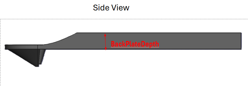 (b) BackPlateDepth (Section 2.4.2)
 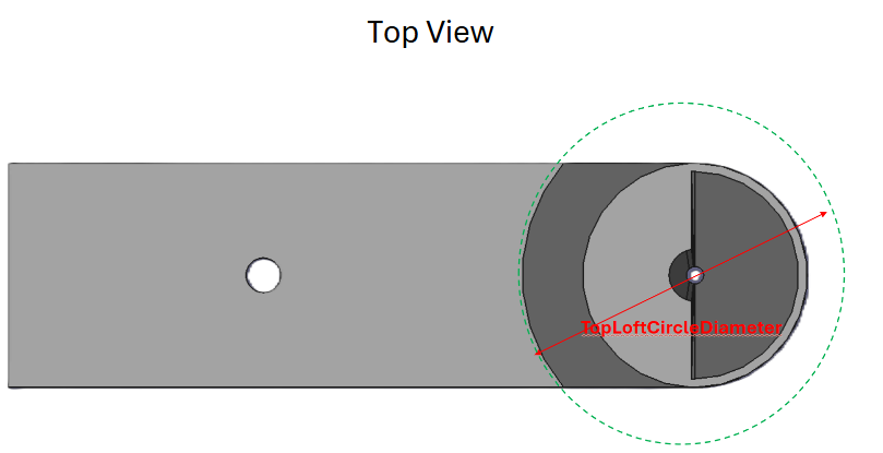 (c) TopLoftCircleDiameter (Section 2.4.3)
 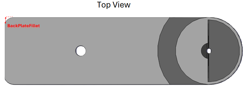 (d) BackPlateFillet (Section 2.4.4)
 BackPlateLength
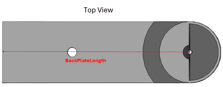
BackPlateLength (default: 40mm) defines the overall length of the entire back portion of the model, starting from the center of the hole in which the fly is mounted, as shown by the red arrow.
This parameter, along with the BackPlateFillet (Figure 6 (d)) and BackPlateDepth (Figure 6 (b)) parameters define the overall shape of the very back section of the model.
BackPlateDepth
BackPlateDepth (default: 2mm) defines the overall thickness of the entire model’s back plate, as shown by the red arrow.
This parameter, along with the BackPlateLength (Figure 6 (a)) and BackPlateFillet (Figure 6 (d)) parameter define the overall shape of the back section of the model.
TopLoftCircleDiameter
TopLoftCircleDiameter (default: 20mm) defines the overall width of the circle above the entire cone, as shown by the red arrow in the image.
This parameter defines the extent of extra space that is given around the cone section and can alter the microscope’s access to the fly.
BackPlateFillet
BackPlateFillet (default: 40mm) defines the overall radius of the fillets on the back of the model
This parameter, along with the BackPlateLength (Figure 6 (a)) and BackPlateDepth (Figure 6 (b)) parameters define the overall shape of the very back section of the model.
Back Plate Hole
 (a) BackHoleDiameter (Section 2.5.1)
 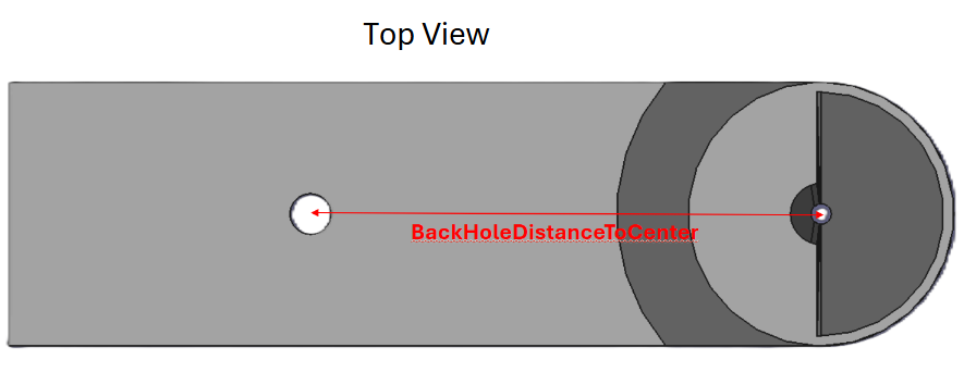 (b) BackHoleDistanceToCenter (Section 2.5.2)
 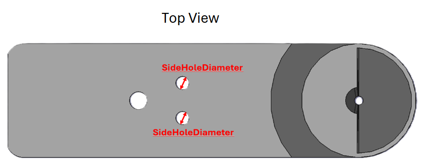 (c) SideHoleDiameter (Section 2.5.3)
 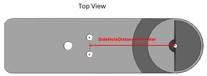 (d) SideHoleDistanceToCenter (Section 2.5.4)
 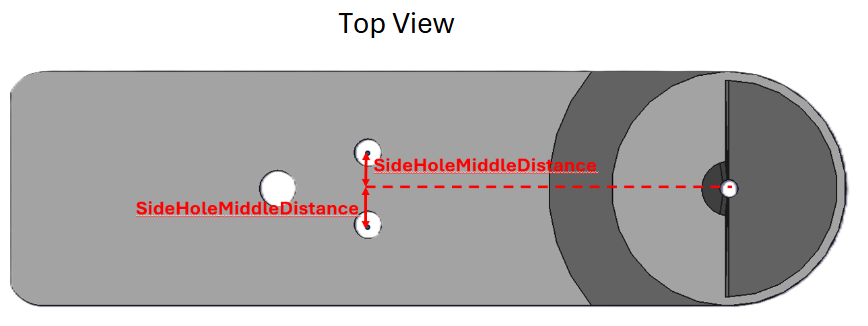 (e) SideHoleMiddleDistance (Section 2.5.5)
 BackHoleDiameter
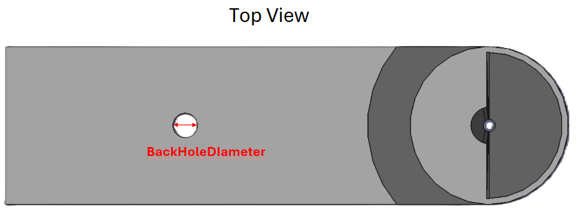
BackHoleDiameter (default: 2mm) defines the total diameter of the hole in the back plate of the model, as shown by the red arrow.
This parameter, along with the BackHoleDistanceToCenter (Figure 6 (b)) parameter, defines the position and shape of the hole in the back plate of the model, which can be used to clamp the fly spoon.
BackHoleDistanceToCenter
BackHoleDistanceToCenter (default: 5mm) defines the total distance from the center of the hole in the back plate of the model to the center of the hole, as shown by the red arrow.
This parameter, along with the BackHoleDiameter (Figure 6 (a)) parameter, defines the position and shape of the hole in the back plate of the model, which can be used to clamp the fly spoon.
SideHoleDiameter
SideHoleDiameter (default: 1.5mm) defines the total diameter of the two symmetric holes in the back plate of the model, as shown by the red arrow.
This parameter, along with the SideHoleDistanceToCenter (Figure 6 (d)) and SideHoleMiddleDistance (Figure 6 (e)) parameter defines the position and shape of the two symmetric holes, which can be used for mounting.
SideHoleDistanceToCenter
SideHoleDistanceToCenter (default: 20mm) defines the total distance from the center of both the symmetric holes to the middle hole of the cone, as shown by the red arrow.
This parameter, along with the SideHoleDiameter (Figure 6 (c)) and SideHoleMiddleDistance (Figure 6 (e)) parameter defines the position of the two symmetric holes.
SideHoleMiddleDistance
SideHoleMiddleDistance (default: 20mm) defines the total distance from the center of both the symmetric holes to the middle of the model of the entire model, centered at the middle of the hole of the cone, as shown by the red arrow.
This parameter, along with the SideHoleDiameter (Figure 6 (c)) and SideHoleDistanceToCenter (Figure 6 (d)) parameter defines the position of the two symmetric holes.
Supports
 (a) Spoon_Support_TopView
 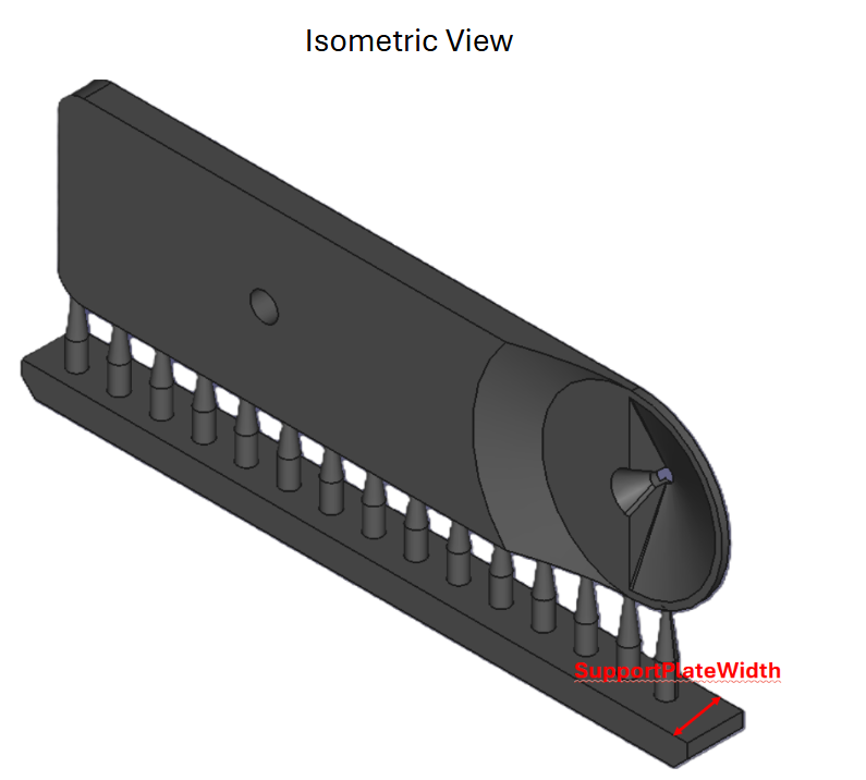 (b) Spoon_Support_Isometric
 SupportDiameter
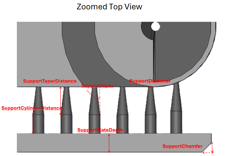
SupportDiameter (default: 0.5mm) determines the overall diameter of each support connecting to the side of the fly spoon model, as shown by the red arrow in Figure 9 (a).
This parameter, along with the SupportTaper (Figure 9 (a)) parameter helps determine the overall strength of each support.
SupportTaper
SupportTaper (default: 7°) determines the taper angle of each support in the model, as shown by the red angle in Figure 9 (a).
This parameter, along with the SupportDiameter (Figure 9 (a)) parameter helps determine the overall strength of each support.
SupportTaperDistance
SupportTaperDistance (default: 3mm) determines the overall distance that each support will continue tapering, before becoming cylindrical, as shown by the red arrow in Figure 9 (a).
This parameter, along with the SupportExtraDistance (Figure 9 (a)) parameter, determine the overall height of each support.
SupportCylinderDistance
SupportExtraDistance (default: 2mm) determines the overall distance of the cylindrical section of the cone, as shown by the red arrow in Figure 9 (a).
This parameter, along with the SupportCylinderDistance (Figure 9 (a)) parameter, determines the overall height of each support.
SupportPlateDepth
SupportPlateDepth (default: 2mm) determines the overall depth of the support plate on the bottom of the model, as shown by the red arrow in Figure 9 (a).
SupportPlateWidth
SupportPlateWidth (default: 4mm) determines the overall width of the entire support plate, as shown by the red arrow in Figure 9 (b).
SupportChamfer
SupportChamfer (default: 1mm) defines the chamfer on the front and back ends of the support plate on the model, as shown by the red arrow in Figure 9 (a).
This parameter allows for the removal of the supports from the build plate to be much easier.
DistanceBetweenCones
ConeCount (default: 15) defines the total number of cones supporting the entire model at the bottom.
Microscope
This section and the stylized objective are only to be used as visualization, and should not be printed or exported into a slicer software. It is instead intended to provide a realistic prediction and image of how the microscope would look with the fly spoon and the possibility of its “intersecting” into the fly spoon with a particular working distance.
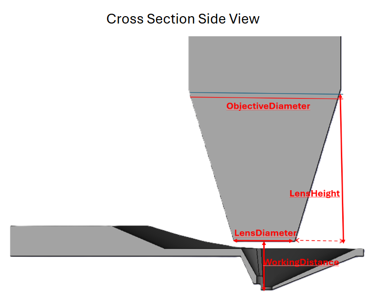 Figure 8: Microscope
 LensDiameter
LensDiameter (default: 4mm) defines the total diameter of the microscope at its very bottom, as shown by the red arrow in Figure 8.
This diameter, along with the ObjectiveDiameter (Section 2.7.2) help define the overall width of the microscope.
ObjectiveDiameter
ObjectiveDiameter (default: 10mm) defines the total diameter of the microscope at the start of the cylinder, as shown by the red arrow in Figure 8.
This diameter, along with the LensDiameter (Section 2.7.1) help define the overall width of the microscope.
LensHeight
LensHeight (default: 10mm) defines the total distance from the lens to the objective and is shown by the solid red arrow in Figure 8.
WorkingDistance
WorkingDistance (default: 3mm) defines the total distance from the bottom of the lens to the bottom of the hole, where the fly will be mounted.
Changing this parameter and the LensDiameter (Section 2.7.1) parameter can cause the microscope to intersect with the fly spoon, indicating a collision in real life with those values.
Print Tutorial Recommended Resins and Exposure Times
Test prints were conducted on the Elegoo Mars 3, Phrozen Sonic Mini 8k, and the Elegoo Saturn 3 Ultra, and all worked well with little difference between each.
Print Instructions
FreeCAD export instructions
 (a) Switch to the *Mesh* workspace
 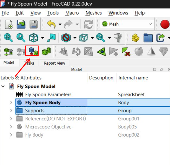 (b)
(b) 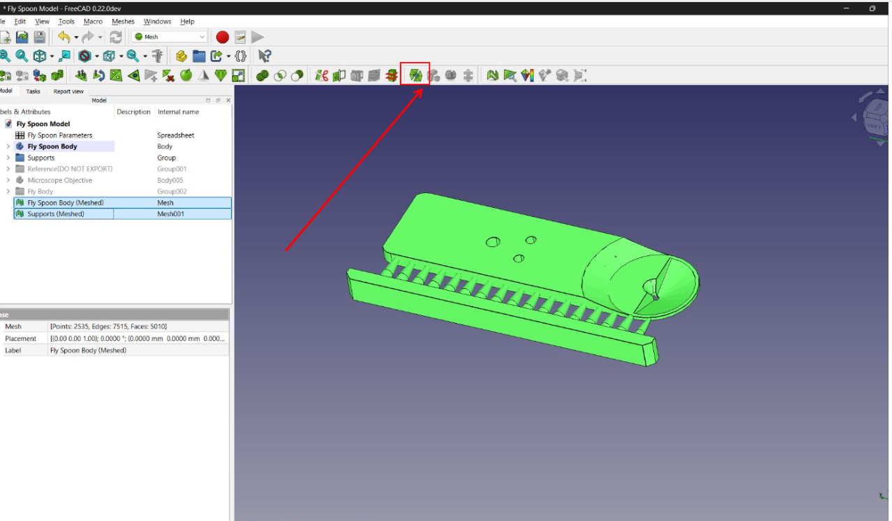 (c)
(c) This can be skipped if FreeCAD is not being used to parameterize the model, and the default 3d files are being used.
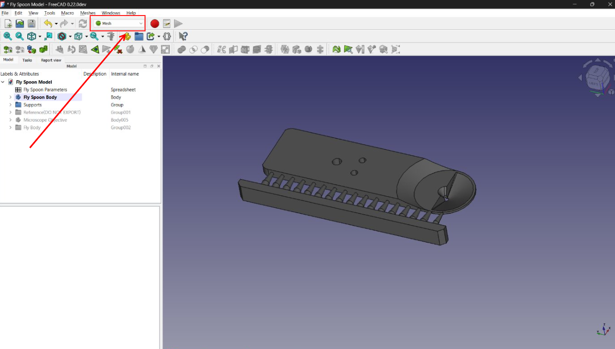
After editing the parameters of the FreeCAD model, exit out to the main menu. Click on the dropdown on the top bar of the screen that says Part Design or Start under the Windows button, and change the dropdown menu to Mesh, as shown below in Figure 9 (a).
After this, select the Fly Spoon Body and Supports folders on the left, as seen below, and click on the Create Mesh From Shape option (see Figure 9 (b)), and select the Ok button with the default settings (default settings were shown to work very well).
After this, select all the new meshes and click the merge button, on the top toolbar, as shown in Figure 9 (c).
With this final mesh, turn off the visibility of all the other objects to make sure that there are no glitches or holes in the design, and then right click on the final singular mesh and select Export Mesh… as a *.stl file. After this, the mesh objects can be deleted.
Slicer Setup Tutorial
The slicer software being used is called Lychee Slicer.
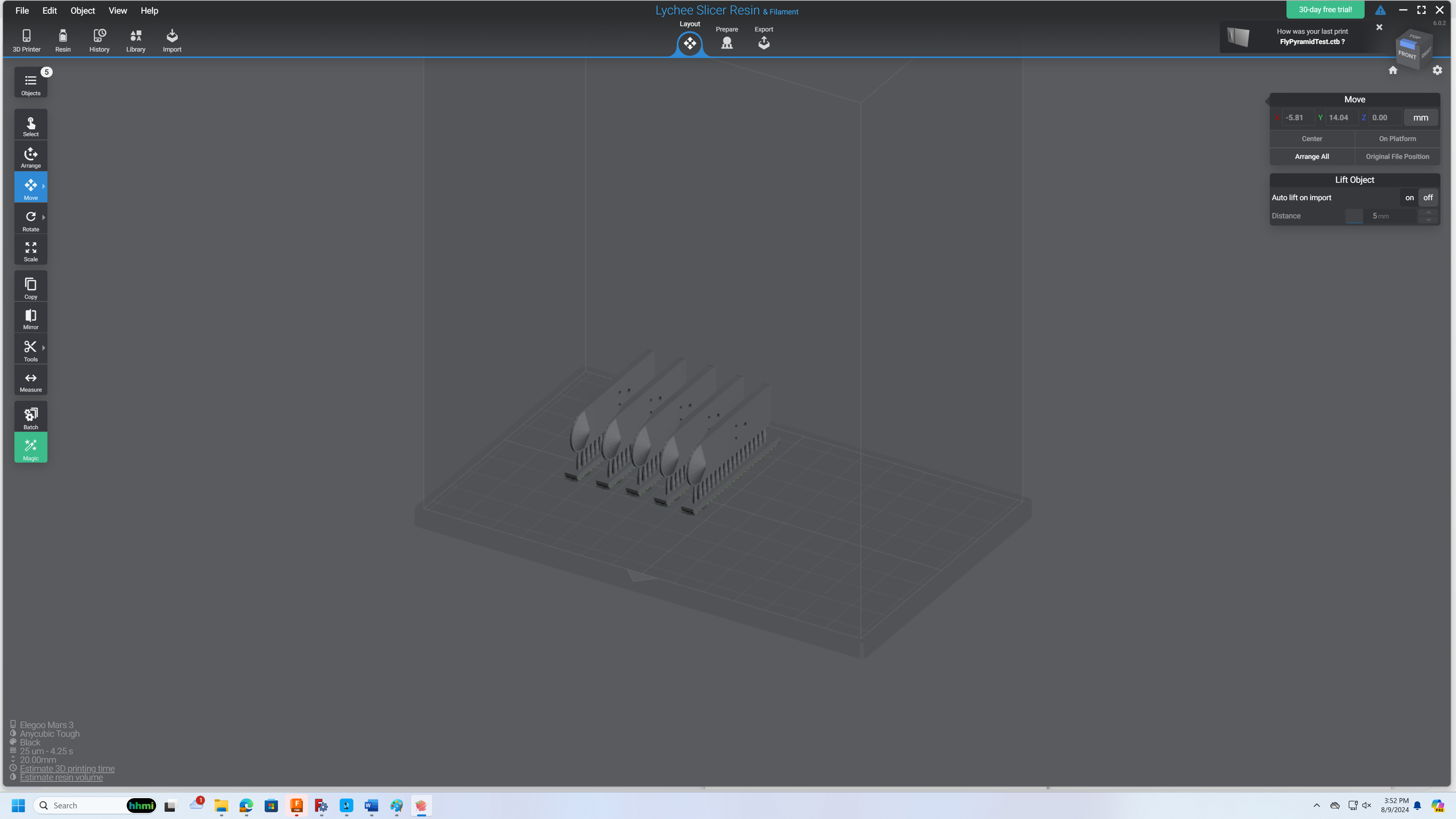 Figure 10: Fly Spoon in the Lychee Slicer
 After setting up the settings of the printer in the software and importing the fly spoon (*.stl or *.obj file) model into the slicer. The fly spoons should be printed individually and not connected to each other, with the bottom supports laying on the plate. However, it is recommended that the fly spoons are printed relatively close to each other, to minimize possible damage from the sloshing of the liquid resin (this is not determined to be a big problem, but it is best to be safe). After this, export the model and print it.
Build Plate Removal
After the prints are finished being printed, carefully remove the build plate from the printer, and lay it flat on the table. After this, use a small razor blade to scrape under the bottom supports near the back of the model, until the bottom supports are loose.
After this, you can wash each of the prints, with either IPA or water (depending on the resin being used), and then cure it for around 5-10 minutes to solidify the resin.
Recommended Resins and Exposure Times
Throughout the course of printing fly spoons, it was tested on. No tests were specifically done on the fly spoons to measure their strength and effectiveness and resin. However, around 60 tests, with different resins, bottom thicknesses, and top thicknesses, were conducted on a similar fly holder model, known as the Fly Pyramid. The information on the strength of these models, which were 3D printed for similar applications and in a similar fashion, can be found under the Fly Pyramid Documentation.
This documentation also includes information found on the specific exposure times and settings of the fly pyramid.
Document History
- originally a Word document by Benjamin Hayworth (Summer intern from Loudoun County High Schools )
- converted to private GitHub compatible Markdown
- converted to quarto Markdown for MCN-NET documentation
- published on Fly-Lab-Gear