Illumination
 → to GitHub project folder The rotation of the spherical treadmill we use in the article about an inexpensive setup is optically tracked through a camera. We use near infrared (NIR) illumination on the sphere since fly vision is insensitive to longer wavelengths while many camera sensors can measure it well. In our setup we use several 840nm LEDs placed between the camera and sphere, pointing at the sphere. The current lamp shade design reduces direct light from the LEDs to the camera sensor. Together with the posts which friction mount in the base plate, the light can be finely adjusted to the sphere. We can also add light diffusers in front of the lamp shade to get a more even illumination of the scene. We provide lamp posts in different lengths, but they can easily be adjusted.
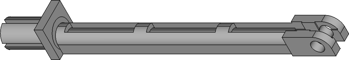
Lamp_post_40.stl: The lamp post comes in different lengths, from 40mm to 100mm. The one in the picture on the right is in between at 60mm length. The image is rotated. On the left you see the split cylinder that can be used as a friction mount in the baseplate. On the right is the mount point for the lamp shade. The center section is hollow to reduce the amount of printing material and can be used to guide the cables from the LED. The length of the lamp post is easy to modify in FreeCAD.
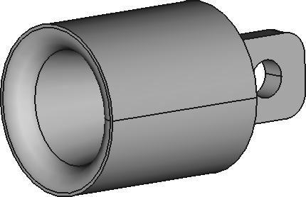 A standard 5mm LED fits well into the lamp shade. There are two holes towards the bottom and mount point to access the anode and cathode. We usually glue the LEDs into the shade. The lamp post provides enough friction to keep the shade in place, but a small screw and nut (eg M2) might help, too.