Preface
The initial version of this document was written by Alice Jiang, who replicated the Inexpensive Treadmill at home and documented the process. If you want to see the overall structure of the document, have a look at the table of contents at the end of the document (to keep the start brief).
1. Ordering Components
A full bill of materials for the fly tethering station and walking setup is available above and may be downloaded as a CSV file. Many components are commercially available off-the-shelf from different vendors. For clarity we linked one potential source for each part, without endorsing this particular provider over others.
2. Ordering/Manufacturing Custom Components
Custom components must be laser cut/3D printed in-house or purchased from a manufacturer. We have tested custom parts from the manufacturers listed in the tables.
Manufacturing custom components involves the use of a laser cutter or a 3D printer. See 2.1 and 2.2 for instructions on ordering parts; see 2.3 and 2.4 for manufacturing.
2.1. Ordering Laser-Cut Parts
Three components of the setup are laser cut: the baseplate, the heat pad plate, and the tethering station. Vector graphics files are linked in the order table. Upload these files to Ponoko or a laser cutting service of your choice. Refer to the components table for acrylic thicknesses, color, and material.
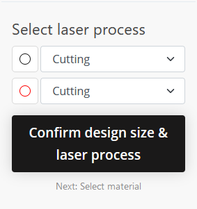
Ponoko will extract paths from the vector graphics file to produce the part. Different colors can have different meanings, but all parts for the setup require lines to be cut. If Ponoko extracts multiple colors, set all line colors to “Cutting” in the drop down menu, as shown below.
2.2 Ordering 3D-Printed Parts
Upload all parts to Craftcloud or a 3D printing service of your choice. All parts need to be printed in mm scale with the exception of the sphere holder files, which are in inches scale and may need to be uploaded separately.
The sphere holder must also be airtight. We recommend printing it in resin, as this requires no additional processing. All other parts may be printed in a material of your choice; we have tested and recommend ABS.
2.3. Manufacturing Laser-Cut Parts
Three components of the setup are laser cut: the baseplate, the heat pad plate, and the tethering station. Vector graphics files for all laser-cut parts are linked in the order table. Upload these to your laser cutting software and set all lines to “cut”. Refer to the components table for acrylic thicknesses.
Many laser cutters and other CAM software require interactions to be paths, whereas most drawing software defaults to objects when generating drawings. A rectangle, for example, can be defined as an object by its two opposing corners or as four connected paths forming a rectangle. Since there are many different types of objects, CNC machines, such as laser cutters, often only interpret the simpler paths and move along them. Therefore, any object in the drawing should be converted to a set of paths. To change a selected object in Inkscape, go to the menu “Path” → “Object to Path”.
The color of a path defines the intensity of the laser for laser cutters. Different colors have different meanings depending on the model and service. Janelia's laser cutters interpret red as cutting, green as engraving, and black as area engraving. Ponoko, one of the services we use, recommends blue for cutting, red for engraving, and black fills for area engraving. The lines themselves should be as thin as possible – a setting of 0.05mm has previously worked well.
Because the cut is so tiny, there are no tolerances or extra material sto consider. The laser beam's power is commonly set in the cutter interface. Acrylic is a widely used material, and many machines let you select the material strength as a proxy for cutting power.
2.4. Manufacturing 3D-Printed Parts
All parts are designed and consequently exported in a metric scale with the exception of the sphere holders, which are in imperial scale. Depending on your printer settings, the adjustments between the metric and imperial system can be achieved by scaling the parts, for example the sphere holders up 2540% in mm scale.
The sphere holder must be airtight. We recommend printing this part in resin, or ordering from a 3rd party service, if possible. Note that the part could also be printed in a material like PLA or ABS and sealed with epoxy or 3D print sealer, though we have not thoroughly tested this. Another alternative is printing in ABS and acetone polishing.
All other parts may be printed in a material of your choice. We have tested ABS and PLA and both are structurally adequate for the setup.
A print guide is listed as an appendix to this document. It contains information on support usage and recommended print orientations for the best possible part quality.
3. Micromanipulator Assembly
A micromanipulator is necessary for both the tethering and walking setup. Since both of these setups require a different arm, we recommend constructing two micromanipulators.
3.1. Components
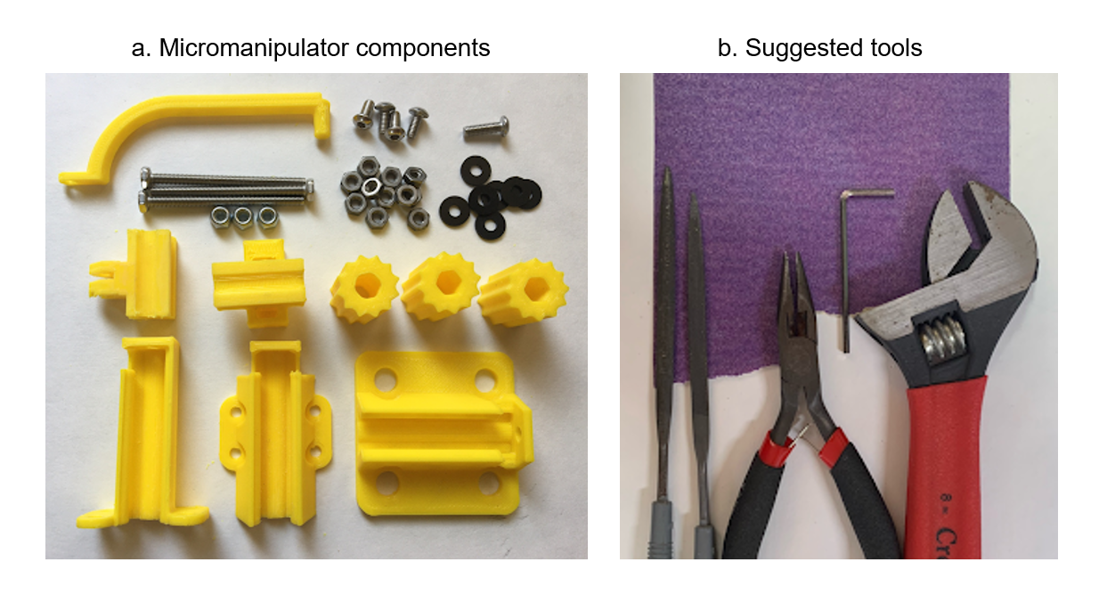
To build the micromanipulator, you will need the following parts:
- 1 x Tether or Arena Arm
- 1 x Top Carriage
- 1 x Center Carriage
- 1 x Top Rail
- 1 x Center Rail
- 1 x Bottom Rail
- 3 x Handle
- 3 x 40 mm M3 Screw
- 1 x 10 mm M3 Screw
- 4 x 6 mm M3 Screw
- 3 x M3 locknut
- 7-10 x M3 nut
- 7 x M3 washer
The following tools will be helpful:
- M3 Wrench
- M3 Screw Allen Key
- Needle-Nosed Pliers
- Sandpaper (fine grit, ~120)
- Needle Files
3.2. Sanding to Fit
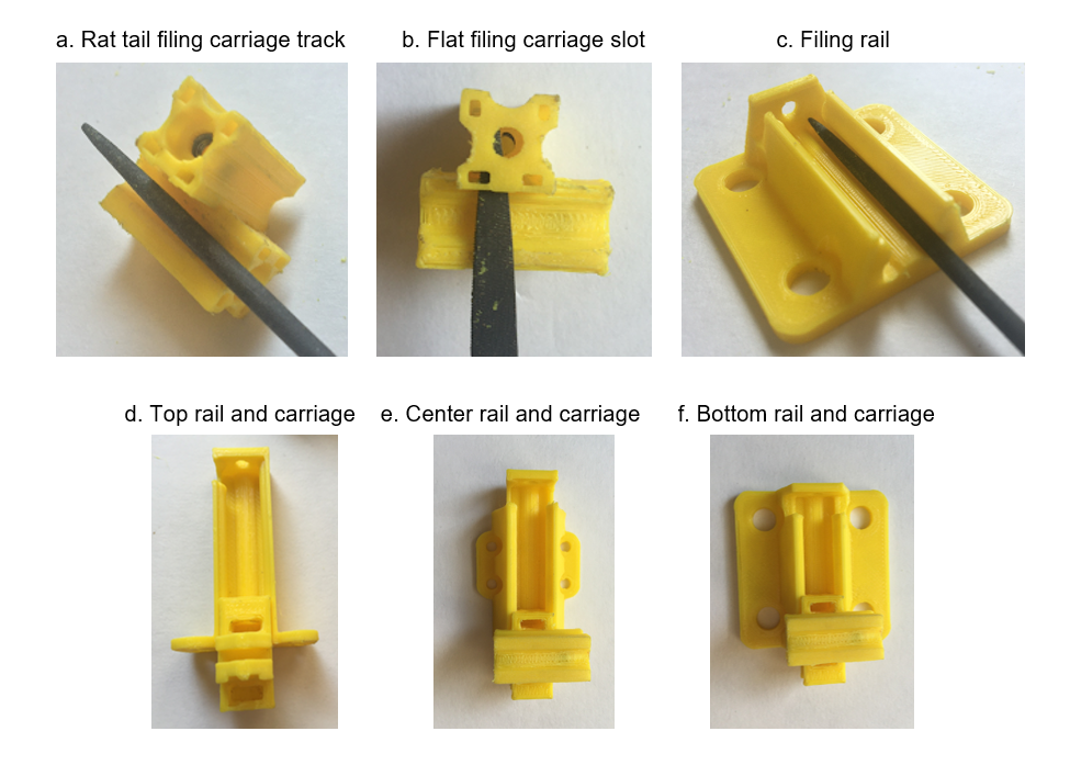
Before assembling the micromanipulator, make sure the sliders and rails slot together correctly. Sand the sides of the slider or the inside of the rail just until you can push each slider into its rail. The easiest way to do this is to use sandpaper on external flat surfaces and rat tail or flat needle files for internal surfaces and corners.
Using a rat tail to smooth the tracks in the carriages (a) and the inside of the rails (c) works well for small adjustments; some friction must be maintained for the micromanipulator to work best. A flat file can be used to file the slots in the carriages to fit M3 nuts (b) and to smooth the insides of rails.
Pay special attention to the open ends of the rails, as print material can build up at the corners and impede the carriage from sliding in through the open end.
3.3. Assembling Top Rail and Carriage
3.3.1. Preparing top carriage
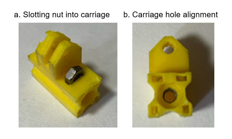
The top carriage has two nut slots. We have found that using only one nut yields the smoothest performance. Load a nut into the slot that is farther from the end of the carriage. Make sure to insert the nut with the flats parallel to the sides of the carriage, shown in (a). When the nut is fully inserted, its hole should be concentric with the hole in the carriage (b).
3.3.2. Loading top carriage into rail
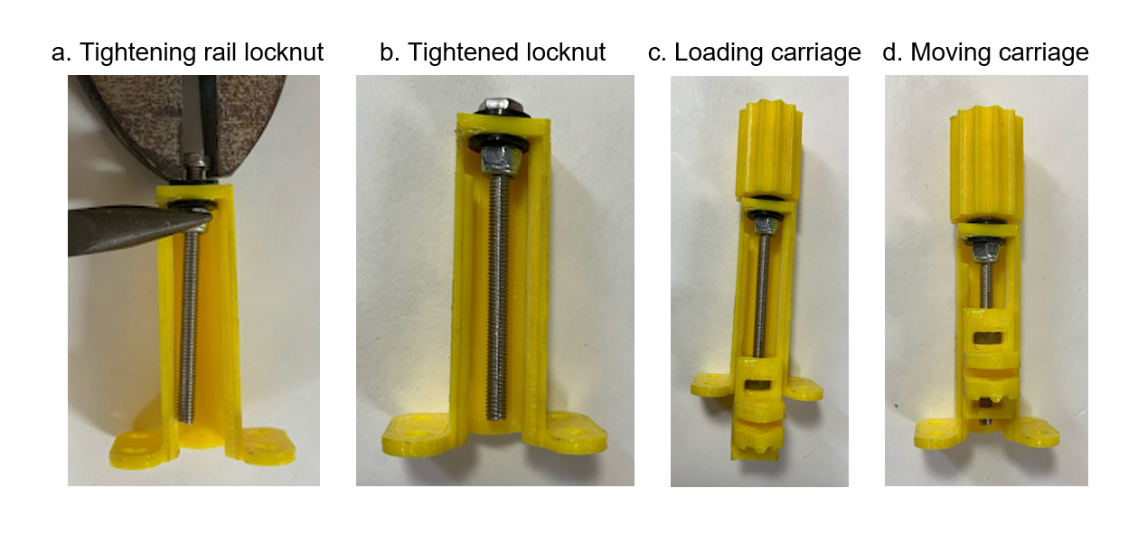
Load a 40 mm M3 screw into the top rail with two washers and a locknut. Tighten the locknut until the hex head, washers, rail top, and locknut are just in contact. This can be done by holding the nut with needle-nosed pliers and wrenching the screw (a). After tightening the nut, the screw should still be able to rotate in the rail.
Push the top carriage into the rail. The slot with the inserted nut should make contact with the screw first (c). Push a handle onto the head of the screw, then turn the handle until the carriage moves up into the rail (d).
3.4. Attaching Center Rail
3.4.1. Preparing center rail
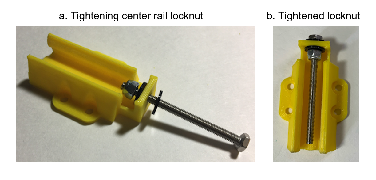
Load the center rail with a 40 mm M3 screw the same way as the top rail, with the nuts and washers in contact but still allowing the screw to turn after the nut is tightened.
3.4.2. Joining top and center rails
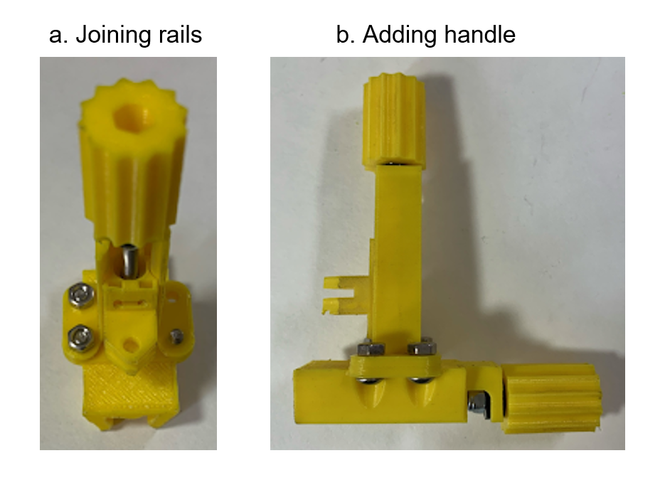
Mount the top top rail assembly on the screw-loaded center rail with four 6 mm M3 screws and nuts. The mounting screws should have the nuts on the top rail so that there is room to wrench them. The hex head of the center rail screw should point towards the back of the top rail (a).
Add a handle to the screw in the center rail (b).
3.5. Attaching Bottom Rail
3.5.1. Preparing bottom rail and carriage
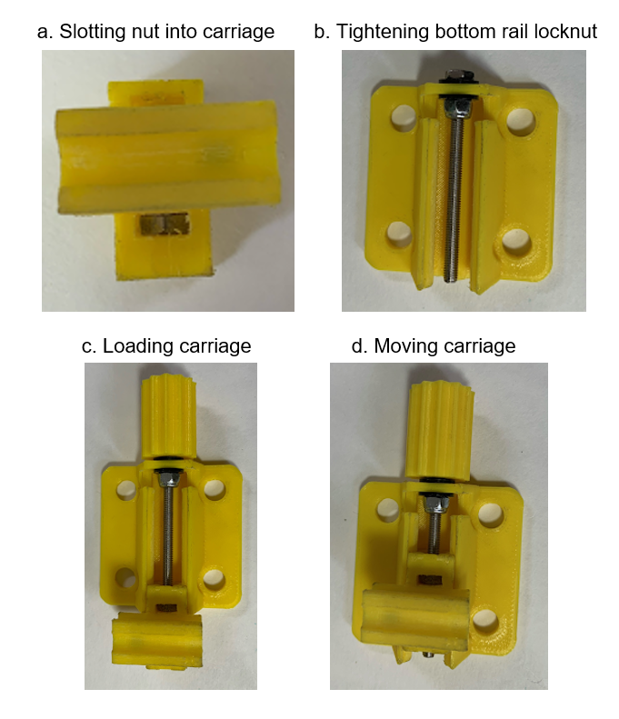
The center carriage has two bars, each of which has two slots. Again, only one nut works best. Insert the nuts into the slot farther from the end of each bar (a).
Repeat the screw loading process with the bottom rail (b). Add a handle to the bottom rail and load the center carriage onto the rail, with the occupied nut slot facing the handle (c). Turn the handle to move the carriage into the center of the rail (d).
3.5.2. Joining bottom and top/center rails
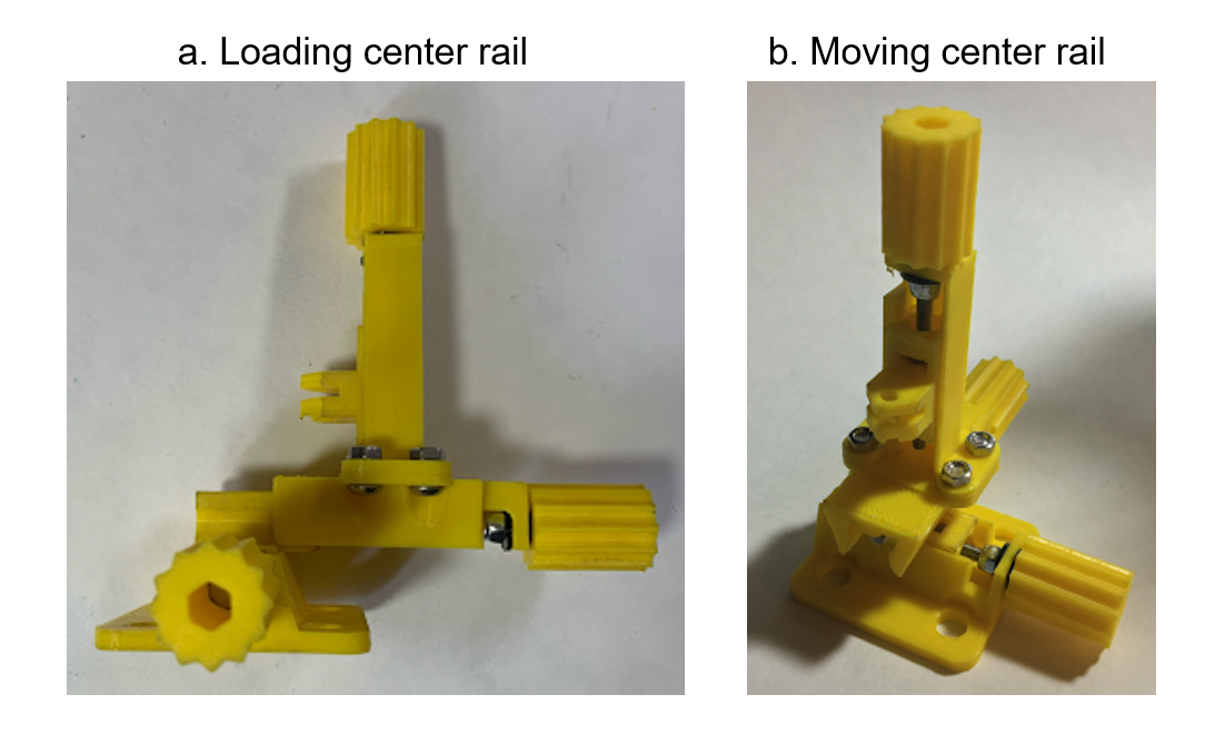
Load the upper bar of the center carriage into the center rail, with the nut slot again facing the handle (a). Turn the center rail handle until the center carriage sits in the middle of the rail (b).
3.6. Finishing Micromanipulator
3.6.1. Installing arm
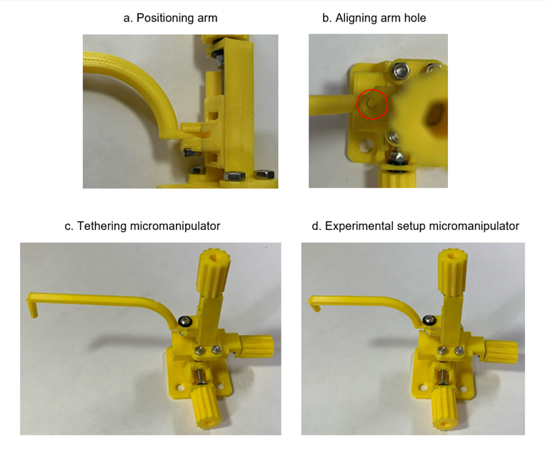
The tethering and experimental setup micromanipulators have different arms. The tethering arm is longer and has an angled tip, while the two arena arms are shorter and provide a choice between an angled/straight tip.
Select the arm for the micromanipulator you are building and nest its mounting tab into the top carriage (a). For the best fit, you may have to lightly file the inside of the carriage and the top/bottom of the tab to remove print artefacts. Nest a M3 nut in the hexagonal recess on the underside of the carriage (a).
Align the hole in the arm with the hole in the carriage and nut (b). Secure the arm with a 10 mm M3 screw and a washer.
A completed tethering micromanipulator (c) and a completed arena micromanipulator (d) are shown below.
3.6.2. Finished Micromanipulators
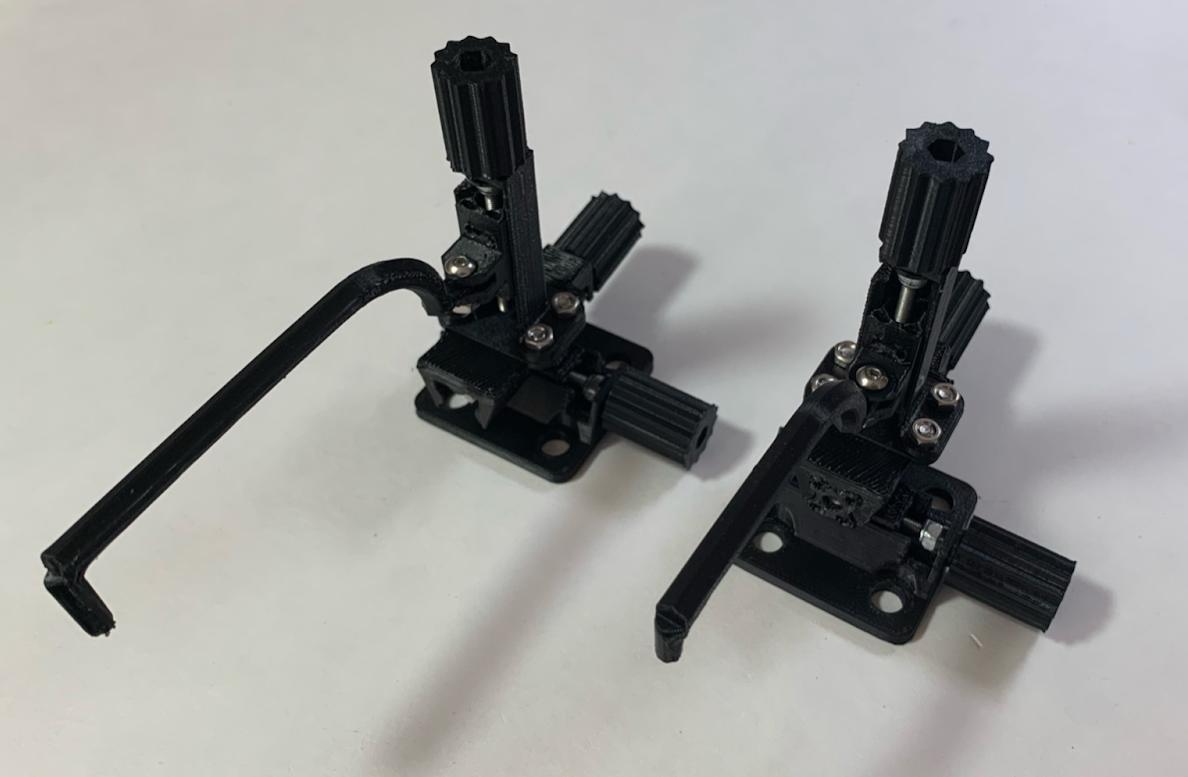
The micromanipulator is complete.
Below are pictures of tethering (left) and arena (right) micromanipulators made from ordered parts.
4. Tethering Station Assembly
The tethering station consists of an acrylic hand rest, on which a micromanipulator and a chiller are mounted. The goal of the tethering station is provide experimenters with a temperature-controlled environment to precisely tether cold-anesthetizes flies.
4.1. Components
TODO
4.2. Hand Rest Assembly
The hand rest is the acrylic assembly that holds together the tethering setup. It will hold the chiller and tethering micromanipulator and provide a place for the experimenter to rest their hand during operation.
4.2.1. Components and Preparation
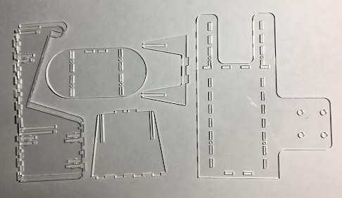
The tethering stand requires a total of six acrylic pieces. You may need to remove backing paper and pop out slots and holes before assembly. Acrylic is prone to shattering, so assemble the pieces carefully. If fits are particularly tight, lightly sanding/filing the slots may help assembly.
4.2.2. Assembling Acrylic Pieces
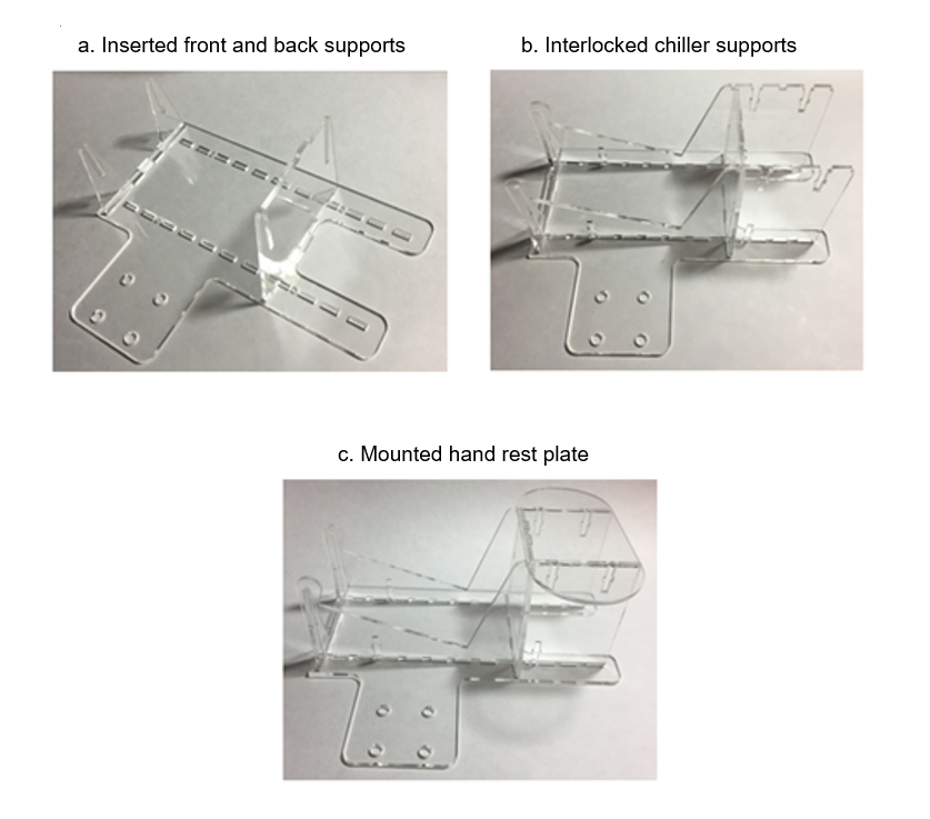
Slot the front and back supports into the baseplate (a). The tabs on the bottoms of the supports should fully insert into the slots in the baseplate. Gently wiggling the parts while pushing them into the slots may help to slide them in without breaking them.
Interlock the chiller supports with the front and back supports and slot their tabs into the baseplate (b).
Press the arm rest onto the back support and chiller supports, making sure to align all the tabe with the slots in the plate.
4.2.3. Securing Hand Rest with Screws
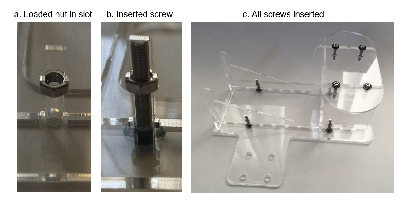
There are eight t-shaped slots in the hand rest. Screws should be inserted in these slots to hold the setup together. Load a nut into the widest point of a slot, making sure its flats are parallel with the sides of the slot (a).
Screw a 20 mm (or slightly shorter) M3 screw and a washer into the slot (b). Repeat for all 8 screws in the hand rest (c).
4.2.4. Installing Hand Rest Feet
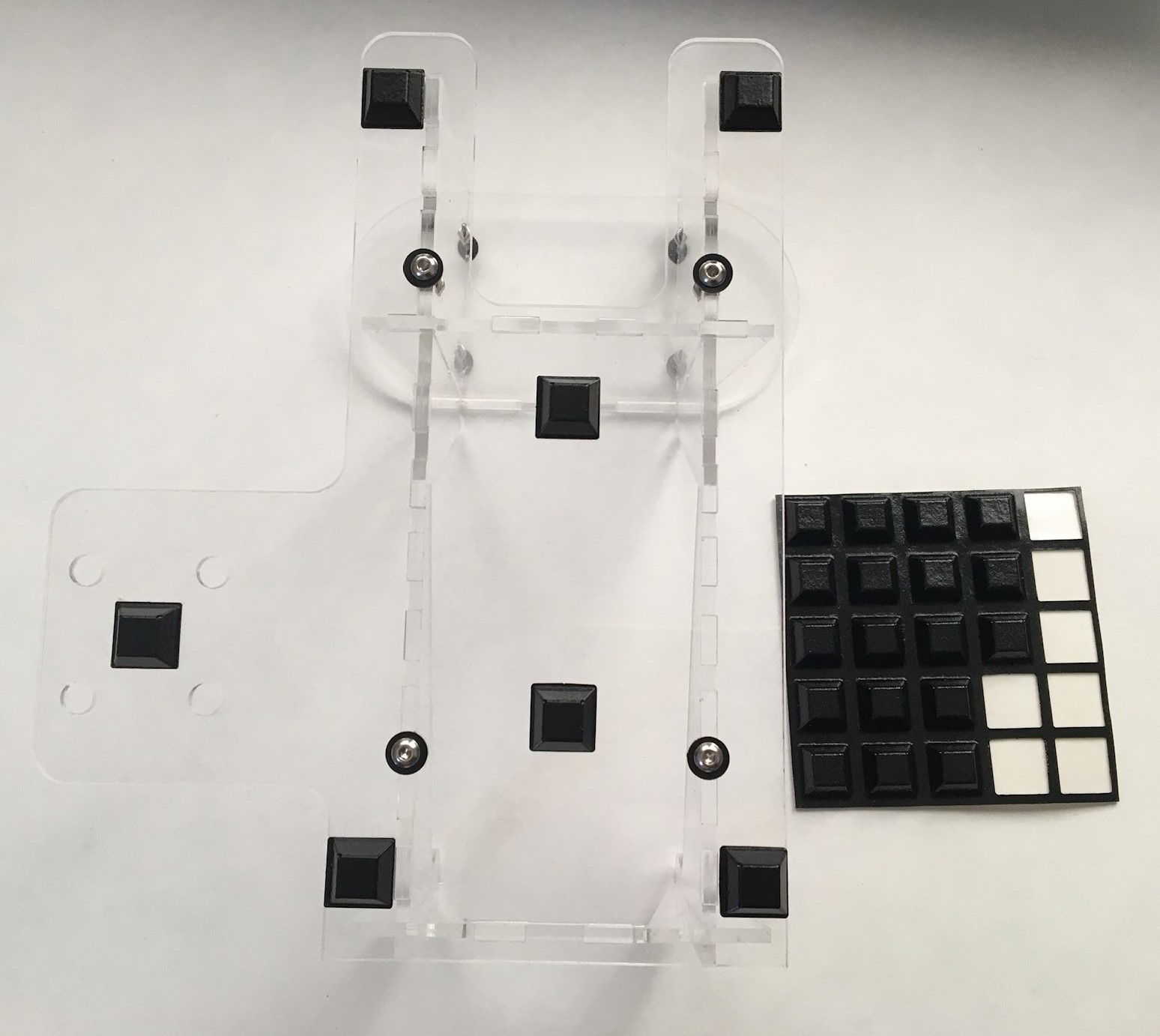
Press several adhesive feet on the bottom of the hand rest. These will keep the screw heads elevated. Be liberal with the feet to prevent bowing between points. An example configuration is shown.
The hand rest is complete.
4.3. Chiller Assembly
The chiller assembly includes a peltier chiller, a “sarcophagus” to hold flies during tethering, and a W1209 temperature controller. You will install the sarcophagus on the chiller and wire the chiller with the temperature controller, thermistor, and power adaptor.
4.3.1. Components
TODO
4.3.2. Assembling Temperature Controller
The W1209 temperature controller that we recommend includes an acrylic housing. We recommend putting the housing together to make handling the controller easier.
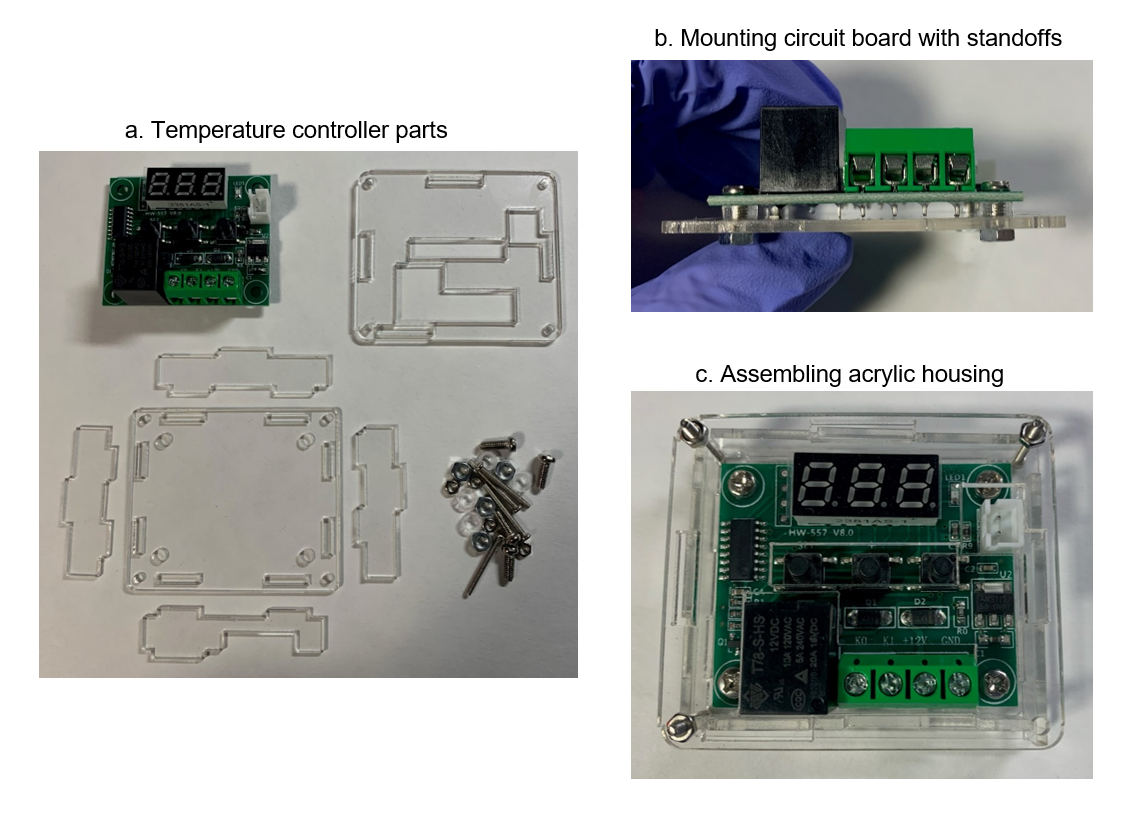
The parts of the housing are shown in (a). Mount the circuit board to the bottom plate with the included short screws and plastic standoffs between the board and plate (b).
Insert the side plates into their slots on the base plate, matching the orientation shown in (a). Place the top plate over the tabs on the side plates. Make sure that the holes in the top plate line up with the components on top of the board.
4.3.3. Wiring Chiller
The chiller must be wired to both the temperature controller and the power supply, via a DC plug adaptor.
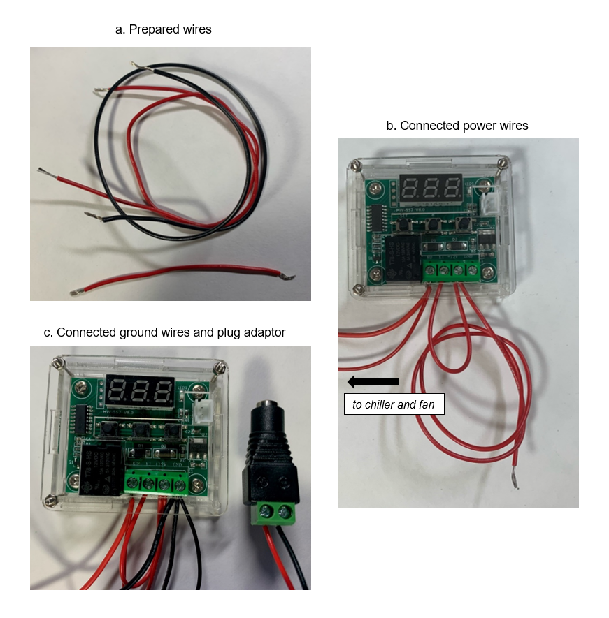
You will need three lengths of cut and stripped wire: one ~3 inch red wire and two ~10 inch wires, one red and one black (a). To insert wires into the terminals, use a small Phillips head screwdriver to loosen the terminal screw until you can insert the wire. Once the wire is inserted, tighten the screw to clamp the wire in place.
Lay the short and long red wires parallel to each other and twist together one stripped end. Insert the wires into the “+12V” terminal, third from the left. Connect the other end of the short wire to the “K1” terminal, second from the left (b).
The chiller should have power and ground wires for both the fan and the peltier unit. Twist together the two red power wires. You may have to trim and strip the wires if they have been tinned. Then, insert them into the “K0” terminal, which is leftmost (b).
Twist together the two black ground wires from the chiller with the prepared black wire. Insert all three wires into the “GND” terminal (c). Finally, connect the two remaining ends of the long wires to the plug adaptor -- red should go to “plus” and black to “minus” (c).
4.3.4. Swapping Thermistor
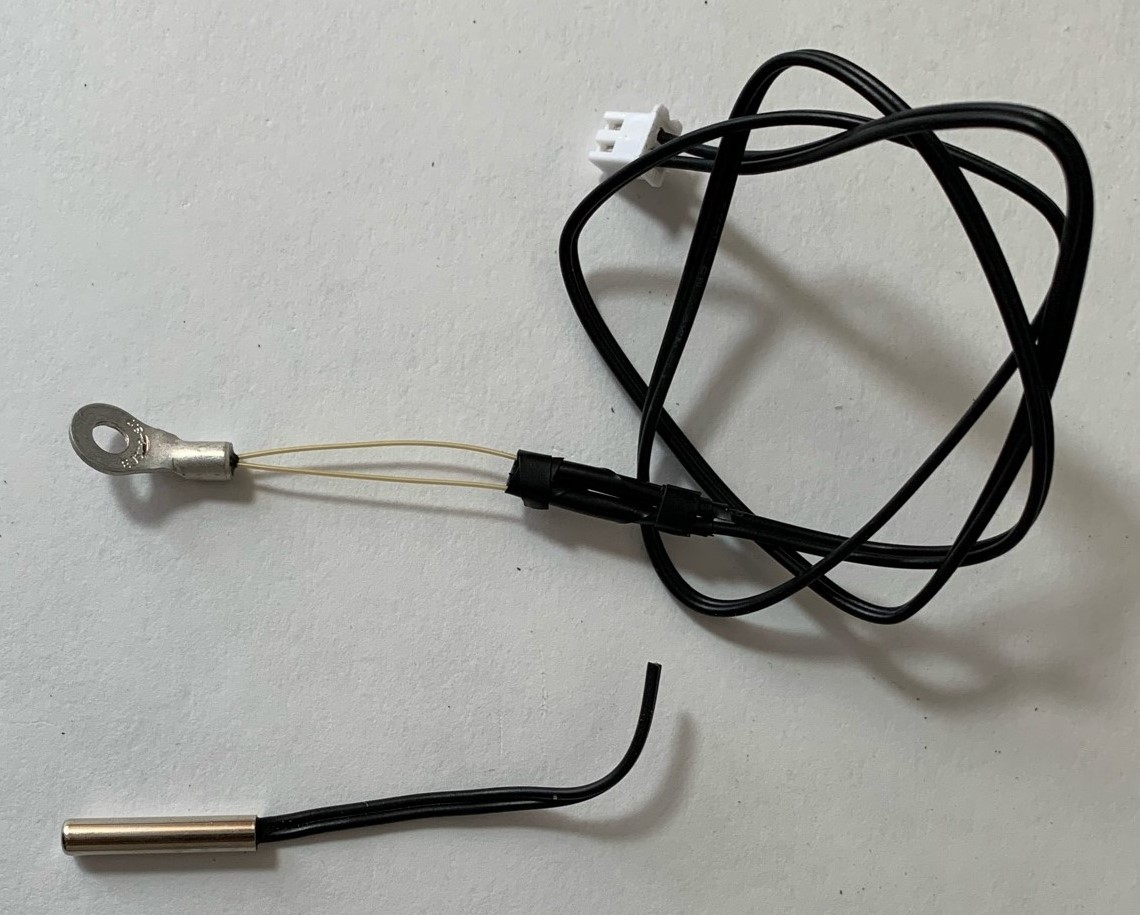
The thermistor that comes with the temperature controller should be swapped out with a ring thermistor. Cut off the rod-shaped end of the thermistor that comes with the controller. Strip the two strands of remaining wire and twist them together with the leads of the thermistor. You may also solder the connection if you wish. Cover the connection with electric tape.
4.3.5. Preparing Sarcophagus
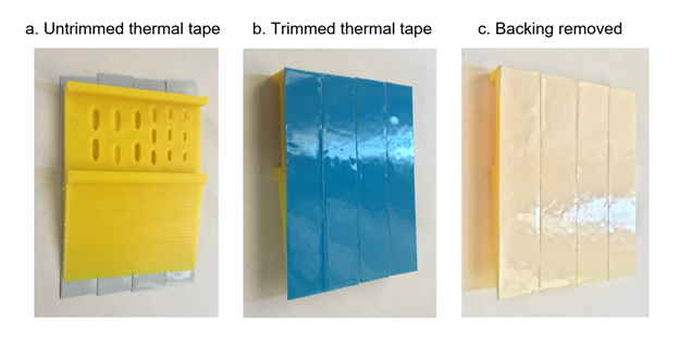
Line the back of the sarcophagus with thermal tape. Try to cover the full surface with tape, with the backing still on (a). Trim the ends of the tape strips to fit the sarcophagus (b), then peel the backing from the strips of tape (c).
4.3.6. Mounting Sarcophagus and Thermistor
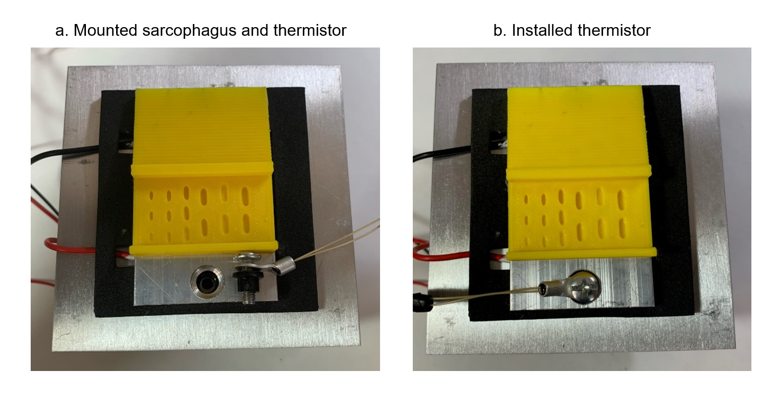
Press the sarcophagus onto the cold plate of the chiller, making sure to leave one of the screws fully exposed (a). Unscrew the exposed screw; it will likely come out with a black adaptor. Remove the adaptor and load the thermistor onto the screw, then replace the adaptor (a). Replace the screw in the cold plate of the chiller (b). Plug the thermistor into its connector on the temperature controller.
4.4. Assembling Tethering Station
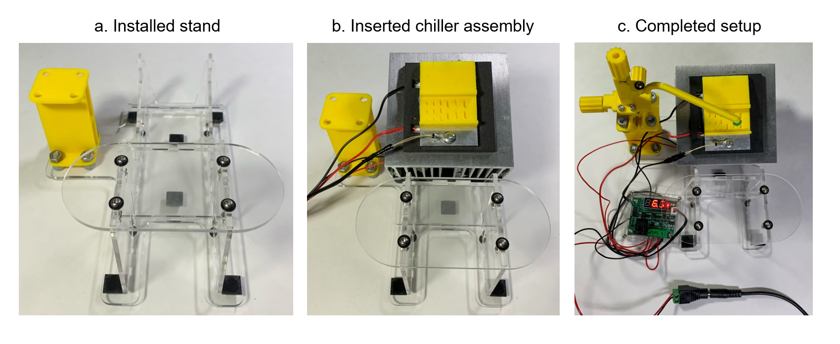
Use four 12 mm M6 screws to mount the micromanipulator stand to the hand rest (a). Insert the chiller assembly into the angled recess in the hand rest (b). Use four more M6 screws to affix the micromanipulator to the stand. This is easiest if the screw heads are facing upwards, with the micromanipulator carriage moved to the center, away from the screw (c).
To use the tethering station, mount a luer needle on the micromanipulator and rotate the arm over the sarcophagus. Plug the power adaptor into a 12V 5A power supply to power the chiller and thermal controller.
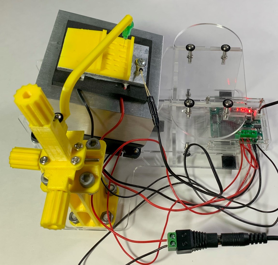
The tethering station is complete. Another angle of the setup is shown below.
4.5. Fly Picker Assembly
Secondary to the tethering station, a vacuum fly picker is useful to move cold anesthetized flies to the tethering station. It can be run off a laboratory vacuum line or with the “deflate” port of a rotary pump.
4.5.1. Components and Preparation
TODO
4.5.2. Fly Picker Tip Assembly
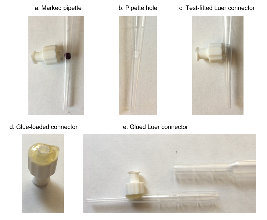
Mark a dot in marker ~1 inch from the end of the pipet. The dot should be roughly the diameter of the inner tube of a luer connector (a). Trim out the dot. This is easiest by making a puncture in the middle and then using the tip of a pair of scissors to snip around the circumference (b). Adjust the hole until it can tightly fit the inner tube of the connector (c).
The connector will be hot glued to the pipette to maintain a good seal. Load the cup around the inner tube of the connector with hot glue, making sure to keep glue out of the tube (d). Quickly press the connector back into the hole and let the glue set (e). Trim off the bulb of the pipette.
4.5.3. Connecting to Tubing
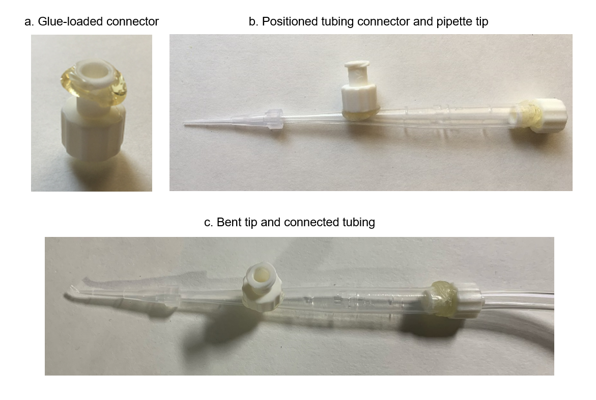
Load another luer connector with hot glue, this time under the rim of the other side of the connector (a). Quickly insert the connector into the back of the trimmed pipette (b). Before the glue sets, gently rotate the connector to ensure that the glue spreads around the inside of the pipette and creates a good seal.
Bend the end of a micropipette tip. Insert a needle or pin in the end of the tip and submerge in hot water or heat with hot air. Carefully bend the tip with the pin, then let the tip cool before removing the pin. Press the tip onto the pipette and connect tubing to the end luer connector (c).
4.5.4. Connecting to Air Pump
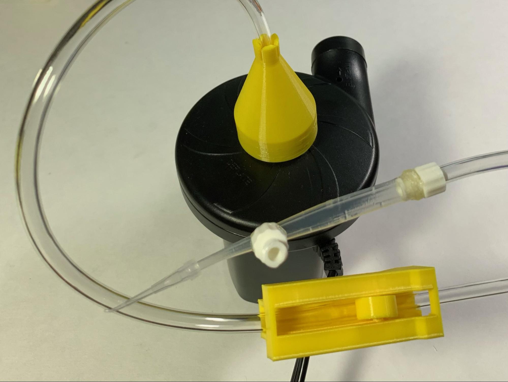
The tubing can be connected to a laboratory airline. If one is not available, we suggest a rotary pump for a similar effect. Add a roller clamp to the tubing for flow control and use the deflate port adaptor to connect the tubing to the pump.
The fly picker is complete. Cover the hole of the perpendicular connector with a finger to pick up flies and release to set them down.
5. Walking Setup Assembly
5.1. Components and Preparation
TODO
5.2. Replacing Camera Lens
The setup uses a PlayStation 3 Eye camera (PSEye) to record the movement of the fly. You will replace the camera’s lens with a new lens at a larger magnification. To do this, you will need a small Phillips head screwdriver, a flathead screwdriver or similar object for prying, and superglue, along with the camera and lens kit.
5.2.1. Removing Back Cover
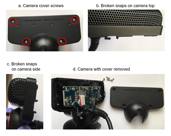
Remove the four screws from the back of the camera. You may have to remove foam coverings, which can be done by prying them up with a toothpick.
Pry the back cover off the camera with a flathead screwdriver, being careful to not damage the printed circuit board. This may result in breaking plastic snaps on the side of the case--this is fine.
5.2.2. Removing Lens
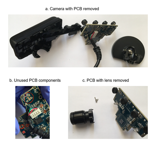
Remove the printed circuit board from the camera face, speaker holder, and stand. The board may be missing components--this is not an issue.
Flip the board over and remove the two screws securing the old lens mount.
5.2.3. Installing New Lens
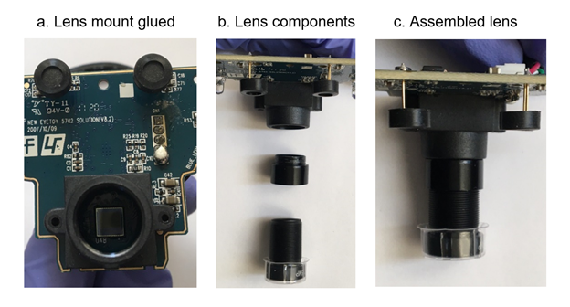
Apply glue to the new lens mount and secure it to the front of the board, aligning it with the silkscreened guidelines.
Screw the extender and the lens into the lens mount.
5.2.4. Replacing PCB
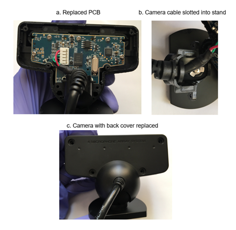
Remove the plastic lens cover and insert the board into the speaker holder, camera case, and stand. Be sure to slot the wire into the stand.
Replace and tighten the screws on the back of the camera. Replace the lens cover to protect the lens while not in use.
5.2.5. Mounting Camera
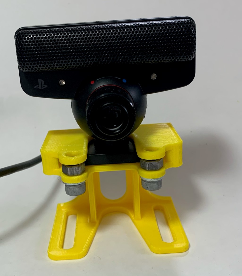
The base of the camera slots into the top of the camera stand. Fix the camera in place with two M6 screws, placing their hex nuts in front of the camera’s base to hold it in place.
5.3. Preparing Heat Pad
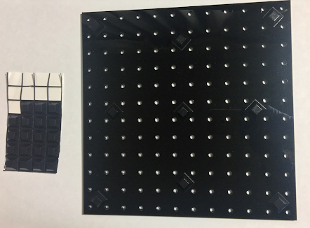
5.3.1. Sticking Heat Pad to Acrylic Plate
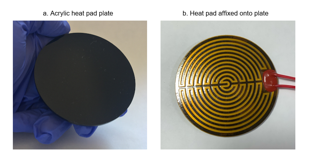
The heat pad is mounted on an acrylic plate (a). Peel the backing from the heat pad and affix it to the plate (b). The heat pad will be facing up, towards the fly.
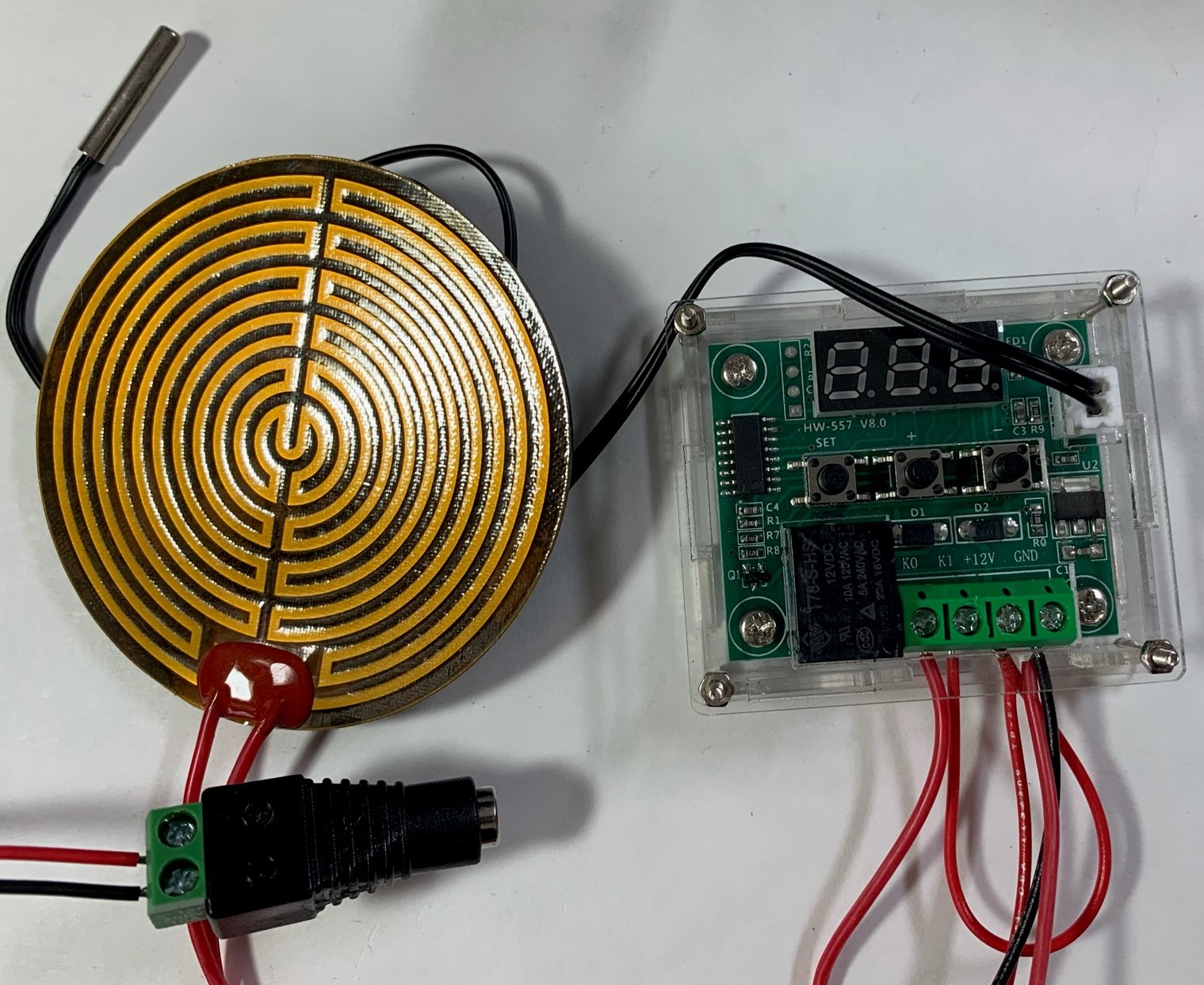
5.3.2. Wiring Heat Pad
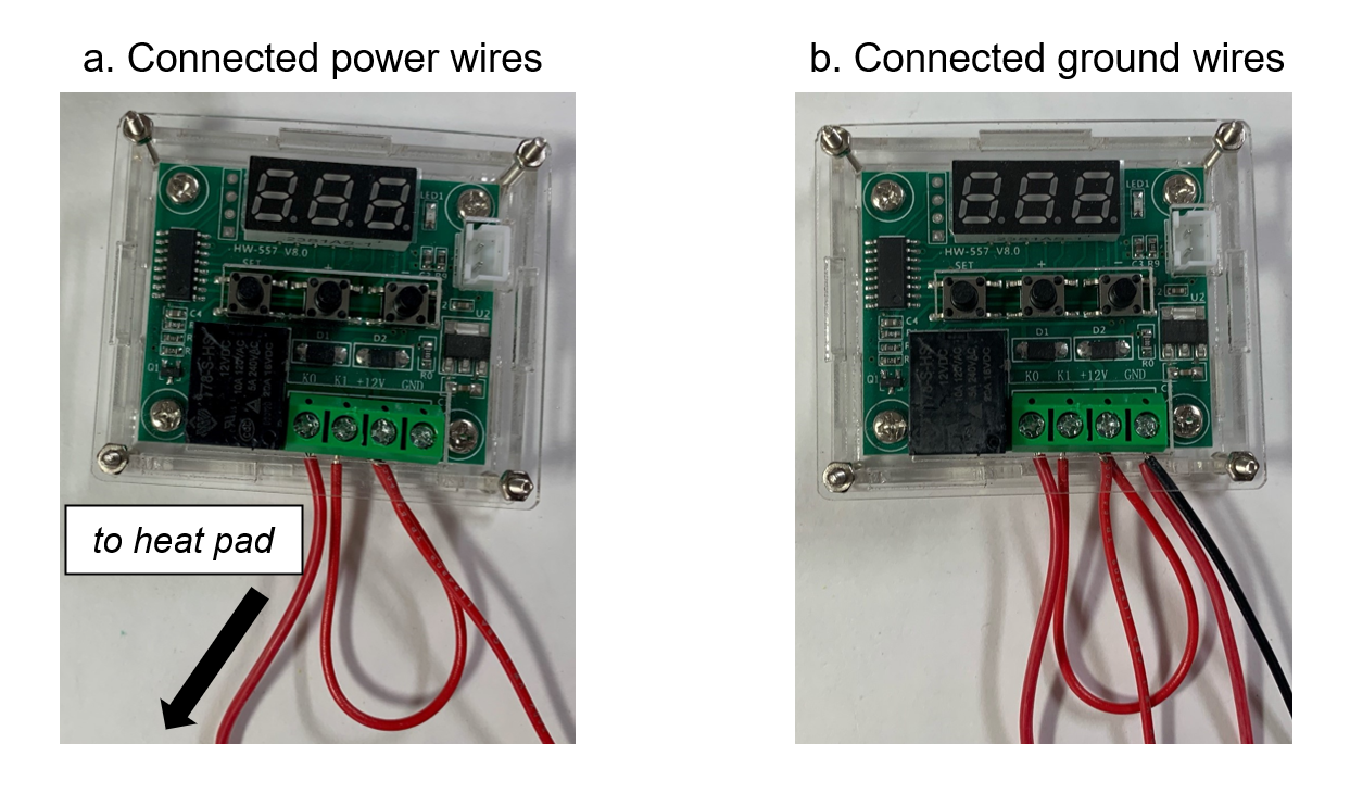
The heat pad is wired to the same temperature controller, the W1209, as the chiller. See sections 4.3.2 - 4.3.3 for instructions on assembling the controller’s housing, inserting wires into the terminals, and the three additional wires that will be necessary for the assembly.
Twist together the short and long red wires and insert them into the “+12V” terminal. Connect the free end of the short red wire to the “K1” terminal. Connect one wire of the heat pad to the “K0” terminal (a). Twist together the other wire of the heat pad and the black wire. Insert them into the “GND” terminal.
5.3.3. Powering Heat Pad
Connect the free ends of the long wires to the power adaptor. Red goes to “+” and black to “-“. Plug the included thermistor into its port. To use the setup, plug a 5V power supply into the plug adaptor.
5.4. Assembling Illumination
5.4.1. Assembling Lamp Posts
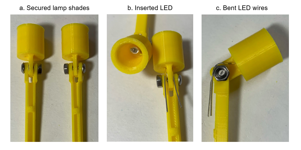
Secure the lamp shades to the lamp posts with 8mm M3 screws (a). Insert an IR LED into each lamp shade, with its leads sticking out through the holes (b). Holding the leads of the LED to the lamp post, angle the shade to its desired position, bending the leads (c).
5.4.2. Wiring Illumination
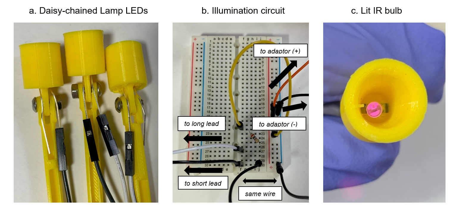
It is easiest to wire the setup if all LEDs are daisy-chained together in series. The LEDs we recommend are polarized so that the long lead is power. Use Female-Female jumper cables to connect the short lead of one LED to the long lead of another, until only one short and one long lead are exposed (a). Make sure that the leads do not contact the screws or nuts; some electric tape or heat shrink may help for this purpose.
Build the illumination circuit shown in (b). The resistor can be changed to fit your needs. A range from 470 Ohms to 3 kOhms seems to work well.
IR light is not visible, but most cameras can pick it up. Use the PS Eye or a phone camera to look at each bulb to verify that they are working properly (c).
5.5. Assembling Baseplate
Place rubber feet on the bottom of the acrylic baseplate. Be liberal with the feet in order to prevent bowing of the baseplate.
6. Software
The setup uses FicTrac to analyze the movement of tethered flies. We recommend running FicTrac on a Linux operating system, or in a Linux VM on another operating system. We have not yet run FicTrac on other operating systems at the desired fidelity but are currently working on this.
6.1. Camera Driver
No camera driver is needed for Linux.
We have not gotten FicTrac to run on Windows at the desired frames per second. However, the camera can connect to FicTrac after installing the CL Eye Driver and then the PSEyeDriver.
6.2. FicTrac
FicTrac is the tracking software used to track the fly’s motion.
6.2.1. Installing VM
If you are working with a non-Linux operating system, we suggest installing VirtualBox VM. Detailed instructions for this procedure can be found here: https://brb.nci.nih.gov/seqtools/installUbuntu.html.
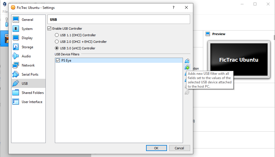
To connect the USB camera to the VM, you will also need to install VirtualBox Extension Pack on the host machine. It can be found here: https://www.virtualbox.org/wiki/Downloads.
Navigate into the Settings menu and enable USB 3.0. Connect the PS3 Eye to the host machine and hit the “Add USB Filter” button to select and add the camera.
6.2.2. Installing FicTrac
We have a branch of FicTrac that allows the camera to be read in low resolution/high frames per second mode. It can be found here:
Install FicTrac on the Linux operating system according to the instructions on the GitHub page:
The instructions suggest building FicTrac with cmake in the “build” directory of a FicTrac clone. If this does not work, try building in the main fictrac directory instead.
6.2.3. Configuration File
FicTrac provides a configuration GUI for orientation information. However, it must still be fed some basic information about the setup to operate.
In the fictrac/bin director, set the following options in the config.txt file:
src_fn           : 0
src_fps          : 187
src_height       : 240
src_width        : 320
vfov             : 5
src_fn controls the USB input channel. If 0 does not work, increment up by one until the camera is recognized. src_fps gives the frames per second -- 187 is the highest the camera can output at the lower resolution given by src_height and src_width. Finally, vfov is the field of view of the camera, which is 5 degrees for our recommended lenses.
6.2.4. Running FicTrac
First, position the camera so that it is focused on the ball. This can be done with any camera software that recognizes the camera; Linux’s native “Cheese” works.
There will be configGui and fictrac executables in the fictrac/bin directory. Run the configGui to equip the software with spatial information. After running through the GUI, run fictrac to begin tracking.
6.2.5. Recommended Settings
If you are receiving suboptimal frames per second, we recommend turning off the display and lowering the q factor from the default 6.
do_display        : n
q_factor          : 3
6.2.6. Windows Errors
We also installed FicTrac on Windows 10. Documentation of errors we encountered follows.
Errors may occur when installing dependencies with vcpkg. Some of these errors seem to stem from the package ffmpeg and cause the dependency installation to run indefinitely.
To get around this, try isolating the install to ffmpeg without the other packages with: .\\vcpkg install ffmpeg\[x264\]:x64-windows
This may result in an error message. A second run of the same command seemed to spontaneously fix the issue.
Additionally, installing packages seems to require keyboard input after unspecified amounts of time, but does not prompt for them. Periodically hit the “enter” key if the install seems to stagnate.
The instructions suggest building FicTrac with cmake in the “build” directory of a FicTrac clone. If this does not work, try building in the main fictrac directory instead.
6.3. FlyFlix Stimulus presentation
Install the FlyFlix software by cloning the FlyFlix repository. Follow the instruction on the repo readme to start the server. Make sure that the tablet is in the same network as the server and point the webbrowser to the server’s IP address and port 17000, for example http://10.10.10.1:17000. Select the experiment you want to run, click on the fullscreen button and then the start button. Some experiments require FicTrac to run in the background.
Appendix: Print Production
This appendix contains recommended print orientations and support usage for all 3D printed parts in the setup.
A.1. Print Settings
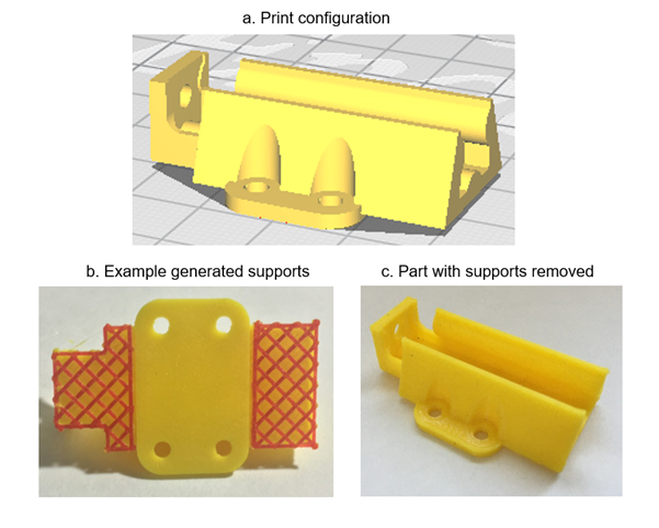
If you have a printer that is capable of producing soluble supports, print with supports everywhere (touching buildplate and touching part) for optimal part quality. If you will have to manually remove the supports (i.e., your printer only extrudes one material), follow the support instructions listed for each part. Support appearance will depend on the slicer used; example supports are shown in red in the pictures.
Printed parts have been tested on a Creality Ender 3 Pro, with Hatchbox PLA. Parts were sliced with .2mm layer height and 20% infill.
A.2. Removing Supports
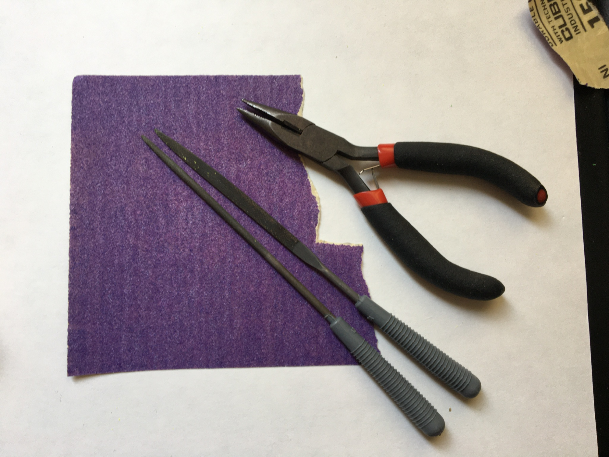
Print supports can be difficult to remove. The correct tools will make this process much easier.
In particular:
- Needle-nosed pliers can be used to grip supports and pull them off. Do not worry about damaging support material with the pliers -- it will be tossed anyways!
- Small flathead screwdrivers can be used to pry supports from the part at the face of contact. This is particularly useful for parts with a lot of support contact, like the micromanipulator center rail.
- Sandpaper can be used to smooth parts after supports have been removed and to fine-tune parts for good fit.
- Needle files can be used for the same purposes as sandpaper. They are particularly useful for shaping narrow areas, like corners, pockets, and holes.
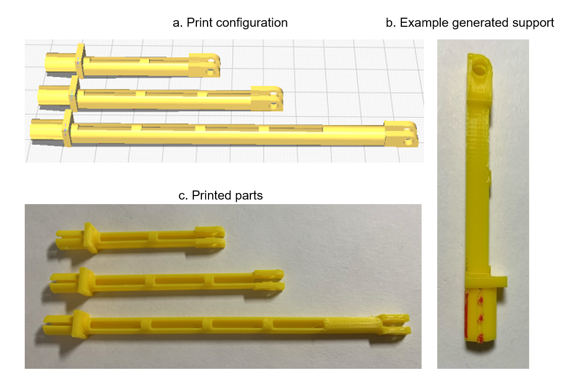
A.3. Micromanipulator Arms
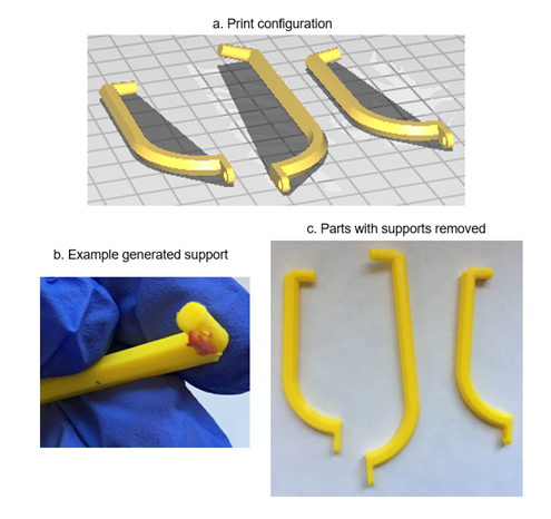
No supports necessary for tethering arm (center).
Supports touching build plate necessary for arena arms (left, right). A support should generate under arm tip and should be snapped off.
A.4. Micromanipulator Bottom Rail
No supports necessary.
A.5. Micromanipulator Center Rail
Supports touching build plate necessary. Supports should generate on the underside of the rail and should be pried off.
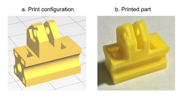
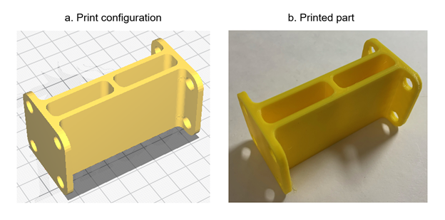
A.6. Micromanipulator Top Rail
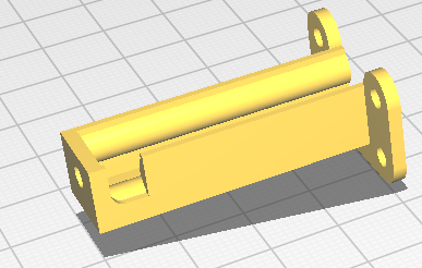
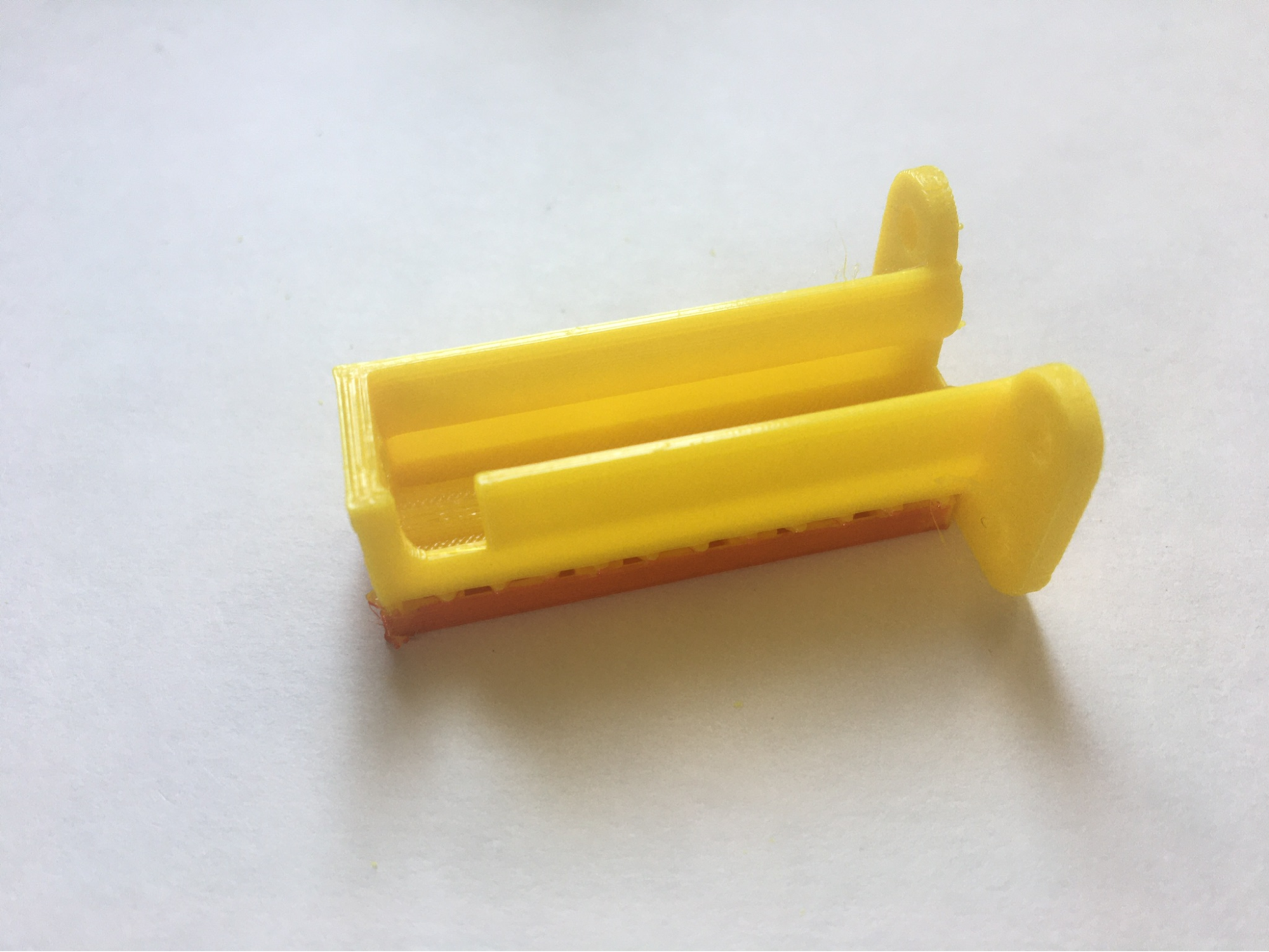
Supports touching build plate necessary. Note that only the back face of the part’s lower plate is touching the buildplate. Supports should generate underneath the rail and should be pried off.
A.7. Micromanipulator Center Carriage
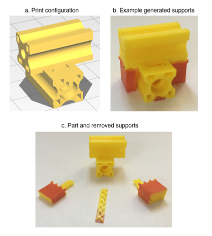
Supports touching build plate necessary. Supports should generate on the underside of the upper bar and underneath the semicircular indent on the lower bar. The lower bar support should be pried off. The larger supports should be carefully loosened from the upper bar, then pulled directly downwards to ensure removal of the support tabs inside the upper bar.
A.8. Micromanipulator Top Carriage
No supports necessary.
A.9. Micromanipulator Handle
No supports necessary. This part benefits from higher infill and/or wall thickness.
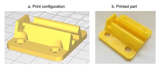
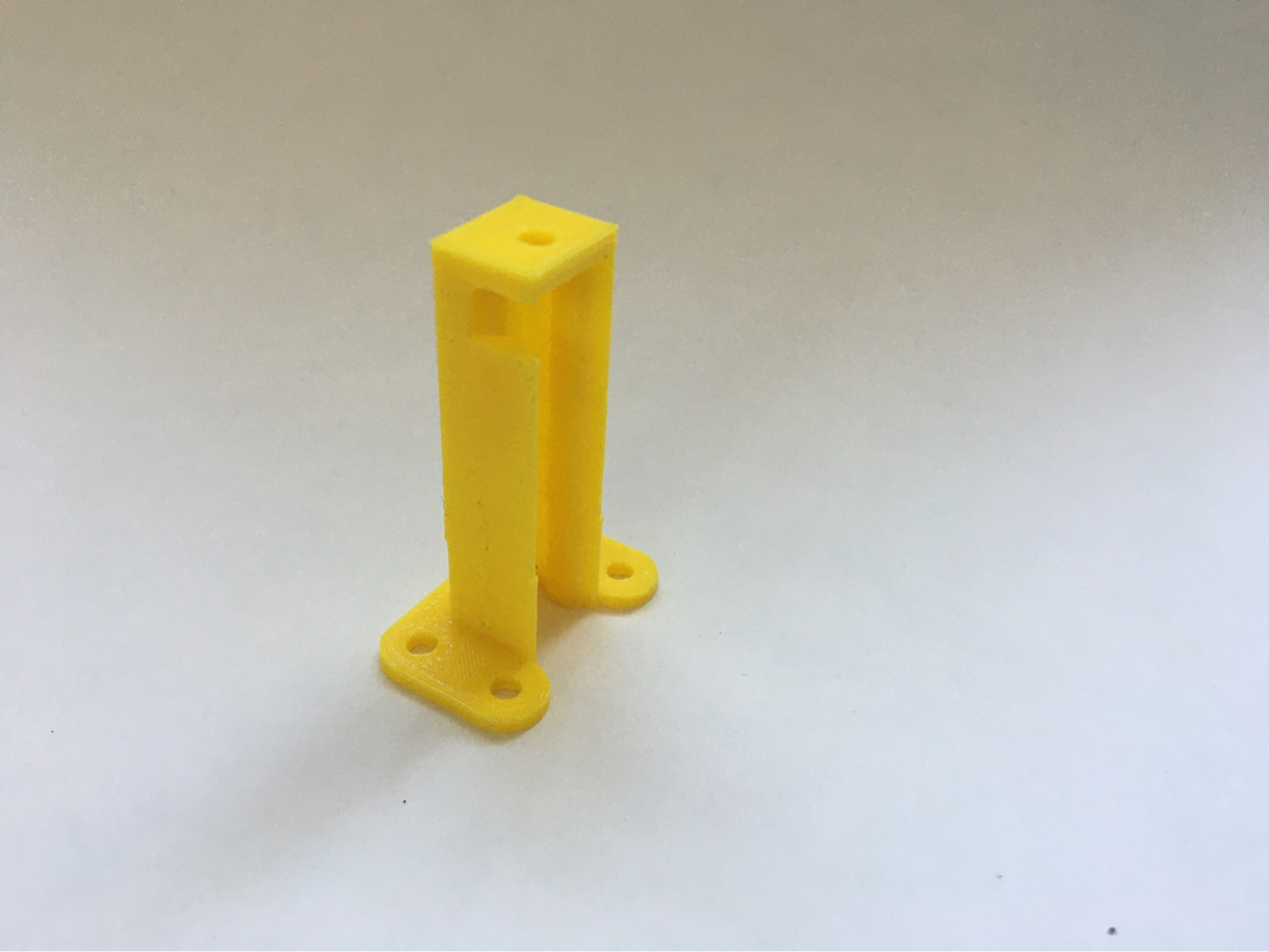
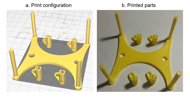
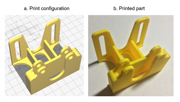
A.10. Micromanipulator Stands
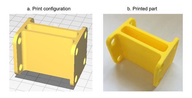
No supports necessary.
A.11. Sarcophagus
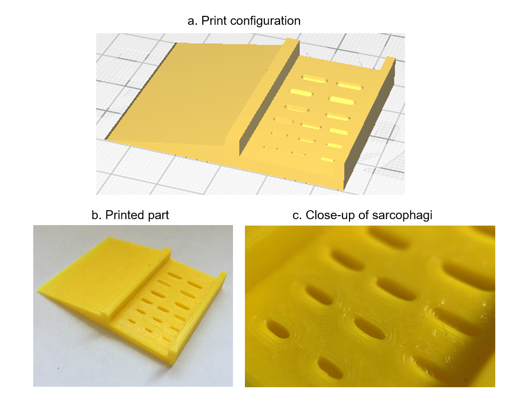
No supports necessary.
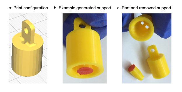
A.12. Funnel
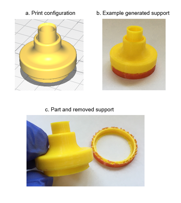
Supports touching build plate necessary. Supports should generate under the rim and should be pried off.
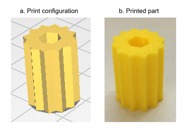
A.13. Sphere Holder
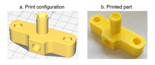
No supports necessary. If the horizontal hole prints poorly without supports, re-print with supports touching everywhere.
A.14. Sphere Holder Stand and Feet
No supports necessary.
A.15. Camera Stand
No supports necessary.
A.16. Lamp Posts
Supports touching everywhere necessary.
A.17. Lamp Shades
Supports touching build plate necessary. Note that the full circumference of the shade’s rim should touch the build plate. Supports should generate under the bell of the shade and should be pulled out.
Table of Contents
This document has the following structure:
- Preface
- 1. Ordering Components
- 2. Ordering/Manufacturing Custom Components
- 3. Micromanipulator Assembly
- 4. Tethering Station Assembly
- 5. Walking Setup Assembly
- 6. Software
- Appendix: Print Production
- A.1. Print Settings
- A.2. Removing Supports
- A.3. Micromanipulator Arms
- A.4. Micromanipulator Bottom Rail
- A.5. Micromanipulator Center Rail
- A.6. Micromanipulator Top Rail
- A.7. Micromanipulator Center Carriage
- A.8. Micromanipulator Top Carriage
- A.9. Micromanipulator Handle
- A.10. Micromanipulator Stands
- A.11. Sarcophagus
- A.12. Funnel
- A.13. Sphere Holder
- A.14. Sphere Holder Stand and Feet
- A.15. Camera Stand
- A.16. Lamp Posts
- A.17. Lamp Shades
- Table of Contents