Classic Tether
 The classic tether initially developed at the Dickinson lab is still being used in many flight experiments. If you are interested in more recent approaches, have a look at the tether section. Since we couldn’t find a good explanation online, here our parts list and step-by-step guide on how to produce them.
For flight experiments, the tether is usually mounted to a brass rod. Depending on your setup, you can cut 0.25” diameter 464 brass rods to the length you require. Attach a Socket Contact Gold Crimp 20-24 AWG (Digi-Key #A2161-ND) to the rod which will act as an adapter to the tether.
The tether is made from three parts that are soldered together. Since the hypodermic tubing is made from stainless steel, we recommend getting some flux for soldering stainless steel as well as using higher temperatures around 350°C (about 650F). Using solder instead of glue allows for easier repairs and corrections by applying some heat, but in general glue should work, too. Some colleagues have apparently used Loctide 4305 (Part number 303389, Legacy part number 32268) in the past. Following the orientation from the adapter on the brass rod to the location where the fly will be tethered, the parts are:
- Pin Contact Gold Crimp 20-24 AWG Machined (Digi-Key #A2160-ND)
- Stainless Steel 316 Hypodermic Tubing: 19 Gauge, 0.042” OD, 0.032” ID, 0.005” Wall, 12” Length (MicroGroup #304H19TW)
- Tungsten wire 127µm diameter, 3” length, 100pc (A-M Systems #716000)
The hypodermic tubing needs to be cut to smaller pieces of 1” length. This requires a precision chop saw or miter saw, otherwise the tubing might get bent and is unusable at the cut end. In that case only two tethers can be made from one hypodermic tubing, the center 10” will be waste.
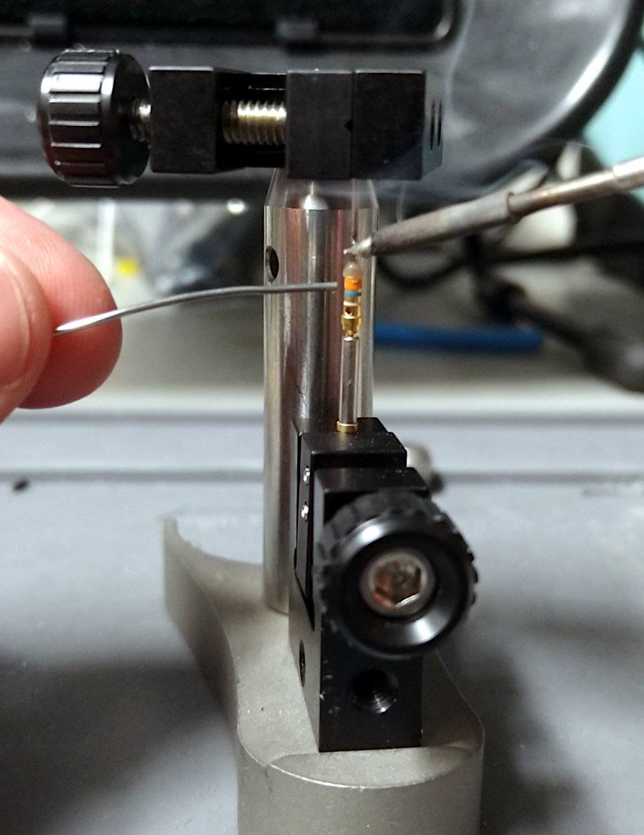
 The first image above shows a little contraption where the bottom clamp holds the same type of socket crimp that is used in the flight arenas at the end of the brass rods. In the picture it holds a contact pin and the top clamp holds the hypodermic tubing in a straight line while I am soldering both parts together. After this step inspect that the connection is straight and sturdy. Since it is soldered, you can correct it by reheating the connection.
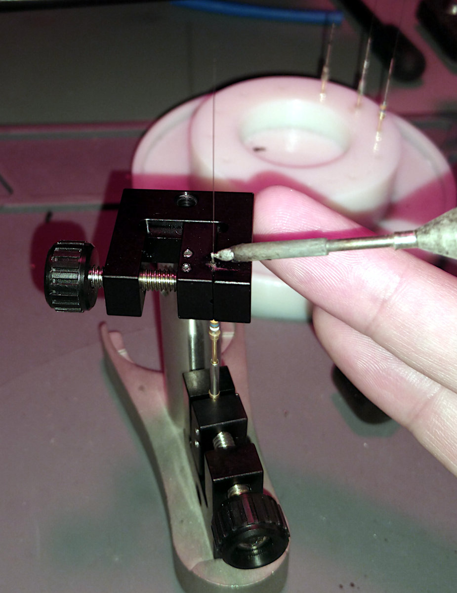
In the second image the hypodermic tubing is exposed above the top clamp and the tungsten wire is already inserted into the tubing as far as possible. In the image I apply some solder to keep it in place. Finally, cut the tungsten wire to the length required in your setup.
Alternative contraptions
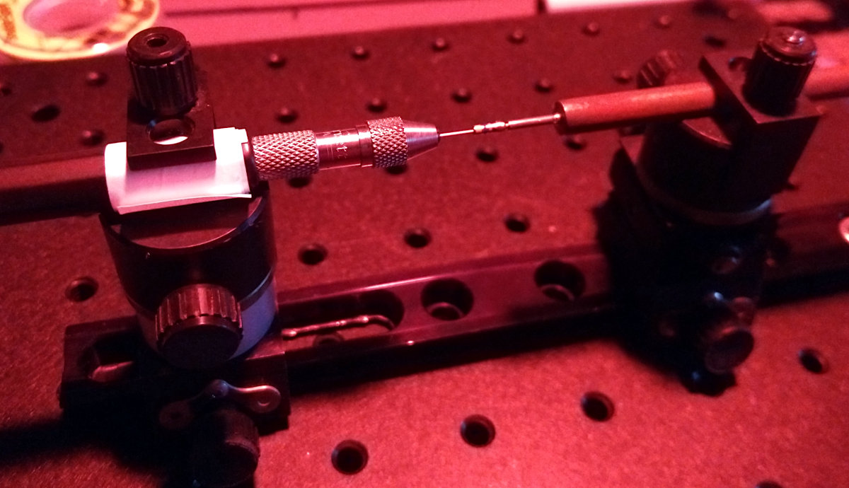 Alternatively to the contraption shown in the images above, we have used other tools in the past. The purpose of all these devices is to center the hypodermic tube inside the pin crimp. The one shown here on the right has horizontal mounts for the tubing (on the left) and the pin (a crimp socket mounted to a brass rod). This is the traditional type that has been around for a long time. It has the disadvantage that the heated solder flows towards one side of the solder joint, creating an off-center weight. Both mounts are moved on a rail.
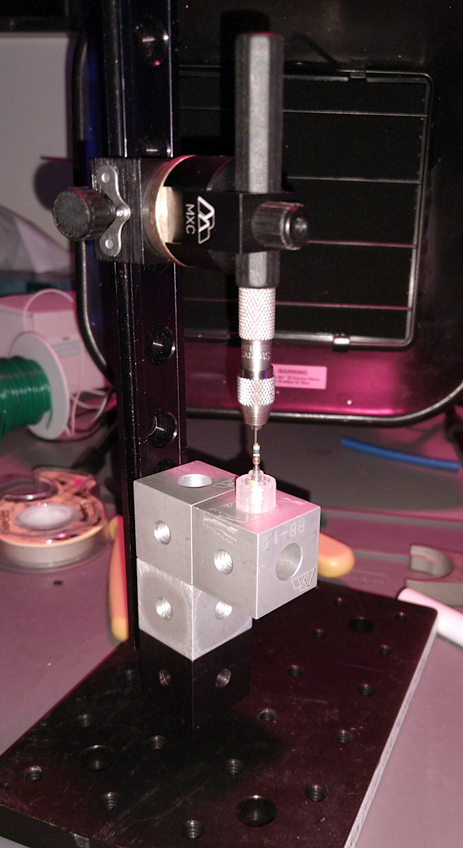 This second alternative uses similar components, but places them in vertical line. This has the advantage of the solder flowing towards the pin, creating a more balanced pin. Furthermore soldering is easier done in this type of setup. Finally, this version uses a socket crimp glued inside a luer lock holder and can therefore double as an aid to solder tungsten wires to blunt tip dispensing needles.
The small contraption used in the images above uses the same principle as the vertical version, but uses two clamps to center the hypodermic tubing inside the pin. All three versions are meant as an inspiration of what you can build from the parts you have lying around. Please send us your pictures if you have any other ideas.